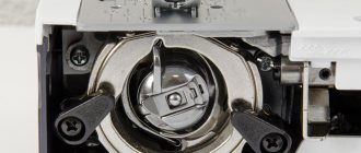
The heart of any sewing machine is the shuttle device. The ease of working with equipment, its reliability and performance depend on it. The design of the shuttles differs from each other (vertical, horizontal, pendulum), they have their pros and cons, which will be discussed in the article. The choice of this element determines what the sewing machine will be capable of.
Description of the shuttle device
In order for the element to remain operational, it needs care
The hook used for a sewing machine is an element that directly interacts with the needle. And the more “accurate” it is, the better the quality of the sewing work. A properly functioning device will not cause skipped stitches, broken threads (upper, lower) or looping.
In order for the element to remain operational, it needs care. For example, if scratches, mechanical damage, rust, dust or oily stains appear on the surface of the shuttle, all this will affect the ability of the thread to slide. This causes the top buckle to be pulled out, causing weak stitch tension.
In stores that deal with sewing equipment and related accessories, you can find a variety of equipment. The shuttles produced differ in design and functions assigned to them.
Horizontal shuttle
The most popular is the rotary horizontal shuttle. The first thing you notice is the ease of threading the bobbin into the hook, as well as the presence of a transparent window on the needle plate to control the remaining thread on the bobbin. The stitch length and seam width (about 7mm) are greater than in a vertical shuttle, which allows for more complex operations. The thread is fed evenly because the shuttle rotates rather than swings. This has a positive effect on the quality of the stitching, especially on thin and elastic materials. Reduces the risk of thread tangling. The horizontal rotary hook requires cleaning, but requires virtually no lubrication.
To get to the adjustment screw, you will have to unscrew the screws that hold the needle plate with a special screwdriver, remove it, and then carefully remove the shuttle capsule. Reassembly and re-inspection will be required to ensure that the tension is set correctly. Therefore, thread tension, as a rule, is not adjusted in a horizontal shuttle.
If you are a progressive beginner and decide to sew clothes for yourself and loved ones, consider a horizontal rotary shuttle, but with a seam width of more than 6.5 mm. It is easy to use and copes better with complex types of fabric.
Principle of operation
The rotation speed can reach 900 rpm, which depends on the equipment settings
The design of the sewing equipment determines what type of shuttle mechanism it contains. Traditional - vertical, which is a cap with a bobbin.
It works like this: a bobbin with thread is fixed in a groove, when the sewing machine starts, the shuttle moves vertically and horizontally, while pulling the thread along with it. Here the lever and the body of the sewing equipment are rigidly connected, so the mechanism is characterized by high reliability.
A vertical type rotary shuttle works differently: the bobbin case, together with the bobbin, moves around its axis.
The rotation speed can reach 900 rpm, which depends on the equipment settings. The good thing about the device is that it can be quickly set up and at the same time has a convenient location to the needle shaft.
The most widespread is the horizontal mechanism, which forms a stitch only after two full revolutions of the shuttle.
There is a built-in bobbin case, so the user is able to quickly “charge” the consumable by simply inserting a spool of thread into the case. The parts of the horizontal device are automatically lubricated, and it is characterized by its quiet, silent operation.
Types of shuttle mechanisms
Horizontal shuttle
Owners of such machines are not interested in the question of how to properly install the shuttle in a sewing machine, since a bobbin without a bobbin case is very easily inserted from above directly into the shuttle. The mechanism rotates around its own axis, the bobbin makes two full revolutions to form a stitch. A transparent plastic window is located on the needle plate and allows you to easily control the color and amount of thread remaining.
Among the advantages of a horizontal sewing machine hook, it is worth highlighting:
- silent;
- does not skip stitches and does not break the thread;
- width adjustment range up to 7mm and stitch length up to 4.5mm;
- ease of control of thread residue;
- the bobbin is simply taken out for replacement;
- no need to lubricate the mechanism.
The disadvantages of a horizontal shuttle include:
- fragility of the mechanism. Coarse threads can damage plastic parts.
- difficulty in regulating the lower thread.
Ease of maintenance and quality of sewing have brought sewing machines with a horizontal shuttle to the first positions when choosing an assistant for home handicrafts. This mechanism is equipped with the A, F and Innov-is (NV) series of the Brother brand, the Bernette series of the Bernina brand, as well as most Janome household machines.
Rotary shuttle
A vertical rotating shuttle is sometimes called a double-circuit shuttle. The main difference from the horizontal mechanism in the plane of placement is that it seems to stand edge-on in the body of the machine. The bobbin is inserted into the bobbin case, and then into the shuttle mechanism. The parts are made of metal - a reliable, durable and wear-resistant mechanism.
Key features of the rotating hook in a sewing machine:
- stitching speed 1000 sti/min without loss of quality;
- increased range of stitch parameters;
- ease and accuracy of settings control;
- low noise and vibration levels;
- reliability and durability.
Among the disadvantages, it is worth noting the higher price compared to machines with other types of shuttle.
A rotating hook in a sewing machine is often chosen for working with a wide range of materials and when high sewing speed is required. Pfaff sewing machines of the Select series, Bernina series 5 and 7, and Brother semi-industrial embroidery machines are equipped with a similar mechanism.
Device types
There are several types of shuttle mechanisms, each of which is good for working with certain tissues. Knowing which shuttle is installed in the equipment will make it easier to use. This is also a key parameter by which sewing equipment is selected.
Horizontal
Horizontal shuttle
Found in most sewing machines sold at an average price. The device is equipped with a rotation mechanism - two full turns form a stitch. There is no separate bobbin case; the bobbin sits directly in the device, which makes threading the lower thread easier.
Advantages:
- the plate with the needle is hidden by a transparent window through which the color of the thread wound over the bobbin and its quantity are visible (it is more convenient for the user to determine when it needs to be replaced);
- it works quietly, looks and is designed simply (no stitches are skipped, needles and threads do not get tangled);
- The machine does not require oil lubrication.
On many sewing machines with a horizontal shuttle, you can adjust the stitches: width - up to 7 mm, length - up to 4.5 mm.
Flaws:
- It is difficult to adjust the bobbin thread. The nut is located on the device itself, which is plastic, so it only works with standard threads;
- The mechanism cannot be modified (only replaced with a new one).
Brother sewing equipment is equipped with a horizontal shuttle mechanism.
Vertical
Vertical shuttle
The classic type of shuttle mechanism (pictured), which was installed in old Soviet cars. Such a shuttle is still found today - in almost all cheap models, as it is convenient, simple and reliable.
It works like this: a bobbin with thread, installed in a cap, is placed in a groove and, when you press the lever, it swings like a pendulum, up and down, drawing the thread with it. The lever is rigidly connected to the body of the equipment, which reduces the likelihood of the shuttle breaking. In this case, the machine can be threaded with any thread, the mechanism will not jam.
The vertical device has two disadvantages: it is noisy and imposes restrictions on the sewing speed. The swinging vertical mechanism is found in machines from Brother and Janome.
The advantage of working with such a shuttle is that the machine is capable of performing many operations, and serious skills are not required.
The swinging vertical mechanism is the choice of creative people who, in addition to sewing, do quilting, embroidery, or create decorations.
Rocking
Swing shuttle
This is a type of mechanism that also uses a bobbin case with a bobbin. The peculiarity of the system is that it rotates around its axis, which is why its second name is “rotational”. The advantage of the solution is the rotation speed, which reaches 1000 rpm. There are other advantages:
- easy to set up and can be fixed “on the needle” without much difficulty. During sewing, stitches are not skipped, the thread does not break, or get tangled. A good machine with a swinging shuttle can work with almost any type of fabric;
- reliability, quiet operation;
- increasing the technical capabilities of the machine: increasing the stitch width to 9 mm, length – up to 6 mm.
Machines with a rotary mechanism are chosen by those who prefer to sew a lot, with virtually no interruptions during breaks.
Sewing machine hooks
The hook of the sewing machine is used to grab the lap loop and move it around the bobbin . The set of shuttle parts assembled with the housing is usually called a shuttle device .
In household sewing machines, shuttle devices with a shuttle that performs reciprocating movements ( oscillating ) have become widespread. rotary) are also used
There are two types of shuttle devices with swinging shuttles:
1) with shuttles (Fig. 7, b), which during the working stroke move clockwise (right-handed). Such shuttles are used in a 1 class straight stitch machine. PMZ and in machines performing zigzag stitches - 116 , 120 , 142 cells. PMZ and others;
2) with shuttles (Fig. 7, a), which during the working stroke move counterclockwise (left-handed). Such shuttles are used in lockstitch machines 1A and 2M class. PMZ. Left-hand shuttle in cars 1A and 2M class. ensures normal weaving of threads in stitches without knots in almost any direction of movement of the materials being sewn. This is especially necessary when embroidering, when the fabric in the hoop is moved in different directions. To understand the principle of operation of shuttles and the purpose of individual elements and parts of shuttle devices, it is necessary to consider the process of stitch formation in machines with various shuttles.
Shuttle device in a machine with a swinging right-hand shuttle.
1 machine ) consists of the following main parts (Fig. 8): shuttle 17, shuttle stroke housing 2, bobbin case 15 with thread tension spring 14 pressed to the cap with screw 13, bobbin 12, cover ring 6, top plate 1, spring 7 with screw 8. The nose 10 of the shuttle serves to capture the loop of the upper thread formed at the eye of the needle. Belt 9 of the shuttle is inserted into the guide ring groove 4 of the stroke body. A bobbin case with a bobbin is put on the rod 11. The shuttle in the guide groove 4 of the stroke body makes a reciprocating movement.
For ease of manufacture, assembly and disassembly, the guide groove of the shuttle stroke housing is open on the rear side and instead of the rear wall, an overlay ring 6 is placed on the pins 3, pressed by a leaf spring 7, which is attached to the housing with a screw 8.
The bobbin is put on the hub of the bobbin case, and the bobbin case, in turn, is put on the shuttle rod 11 and locked with a latch.
The bobbin case remains motionless during operation: it is kept from rotating by the installation pin 16, which fits into the groove 5 of the shuttle stroke housing.
When removing the loop from the shuttle device at the end of the loop formation, a loop of the upper thread passes between the installation pin 16 and groove 5, therefore, in order to avoid chafing and thread breakage, the surfaces of the installation pin 16 and groove 5 must be carefully polished.
The shuttle travel housing 2 is attached to the platform. The position of the guide groove 4 relative to the needle is set very precisely when assembling the machine sleeve with the platform. Greater installation accuracy is necessary so that the nose of the shuttle passes near the needle with a maximum clearance of up to 0.1 mm. The gap between the nose of the shuttle and the needle in this mechanism is not adjustable . As the gap between the needle and the nose of the shuttle increases, skipped stitches occur. To allow the needle to pass to the nose of the shuttle and pass the upper thread, the body of the shuttle stroke from above is partially open and the guide groove is missing for some distance. Plate 1 (thread guide plate) is attached to the top of the shuttle stroke body.
The process of stitch formation in a machine with an oscillating shuttle. In a car 1A class. The PMZ movement of the shuttle (Fig. 9, a - c) is communicated from a special two-arm leash 3 with horns 4 and 6, called the shuttle motor . The shuttle motor, attached to the end of the shuttle shaft, makes a reciprocating movement, which is transmitted to the shuttle by the alternating action of horns 4 and 6. The top thread from the reel is tucked between the washers of the tension regulator 2, then into the eye of the thread take-up 1 and, finally, into the eye of the needle.
To understand the operation of the shuttle device, let us consider the process of stitch formation sequentially .
The needle, lowering to its lowest position, passes the upper thread through the materials being sewn (Fig. 9, a). The nose of the shuttle is at this time in the extreme left position at a distance of 3.5-4 mm from the axis of the needle. Then the needle rises from its lower position by 2.5 mm (Fig. 9, b). On the side of the short groove at the eye of the needle, a loop is formed from the top thread of sufficient width (1.5-2 mm). The greatest width of the loop is formed at a distance of 1.5-2 mm above the eye. In order for the nose of the shuttle to enter the lap loop at this moment, the eye of the needle should be located 1.5-2 mm below the nose of the shuttle.
The wedge-shaped shuttle nose in a 1 class sewing machine. The PMZ passes near the needle on the right, when viewed from the side of the worker (see Fig. 9, b, view A). The needle with its short groove is installed to the right of the worker.
After the nose of the shuttle enters the loop of the upper thread, a very important moment is to move the overlap loop to the base of the nose (putting loop A on the nose of the shuttle 7, Fig. 9, c and d). If, at the moment the shuttle nose approaches the beginning of the guide groove of the stroke body, loop A lingers on the shuttle nose 7 (Fig. 9, e) and does not move to the base of the nose, then it will tighten the loop into the groove and the top thread will break.
The upper plate 5 (see Fig. 9, c) creates an inclination of the loop to the horizontal, helping to move the loop to the base of the spout. The shuttle engine, with its horn 4, presses on the heel of the shuttle, turning it clockwise. At this time, a gap ( a) for the free passage of the loop.
The sewing machine has 1 cl. PMZ this gap is 0.6-0.8 mm. Too large a gap would cause increased knocking in the shuttle device, and with a small gap there would be no free passage for the thread, which would lead to its breakage. There should also be a gap between the lower plane of the shuttle spout and horn 6. If this gap is insufficient (Fig. 9, e), the loop cannot move to the base of the spout and will be dragged into the guide groove of the stroke body with inevitable thread breakage .
Then the shuttle continues its working stroke (Fig. 9,g). Its nose and belt fit into the guide groove of the shuttle stroke body. The base of the shuttle nose, moving the loop, transfers its branches to the side conical surfaces of the shuttle. These surfaces must be thoroughly polished.
With further movement of the shuttle in the same direction (Fig. 9, h), the base of its nose moves the loop to the surface of the bobbin case (from the front side) and the rear wall of the shuttle.
The loop from under the shuttle nose goes to wing 8 (see Fig. 9, e). The shuttle with its entire body enters the loop. In order for the loop to better move from the side conical surface of the shuttle to the surface of the bobbin case, there should also be no ledges on its path (the opening end of the latch should be on the reverse side along the path of the loop encircled by the shuttle).
The base of the shuttle nose (Fig. 9, i) brings the loop slightly further beyond the vertical. At this moment, the eye of the thread take-up lever rises and throws the loop off the hook.
To avoid sudden movement of the lever, the lifting of the thread take-up begins a little earlier. First, the eye of the thread take-up lever rises slowly and selects excess (reserve) thread.
The inclined wing 8 of the shuttle also facilitates dropping the loop from the shuttle.
The shuttle engine stops moving clockwise and begins to turn in the opposite direction. This leads to the fact that the horn 6 of the shuttle engine now becomes the leading one and presses on the base of the shuttle nose. The shuttle begins its idle run. At this time, the loop is almost already wrapped around the bobbin case with the bobbin.
Between the heel of the shuttle and the horn 4 of the shuttle engine, a gap is formed that is necessary for the dropped loop to exit the shuttle device.
Then the thread take-up quickly removes the loop from the shuttle device (Fig. 9k). The loop, inside of which the lower thread is now located, comes out through the gap between horn 4 and the heel of the shuttle. The shuttle, rotating counterclockwise, approaches its heel 9 to the left wall of the window in the shuttle stroke housing. This wall, relative to the line of movement of the needle, should be located at such a distance that when the heel of the shuttle approaches it, the loop is already coming out of the shuttle device, as shown in Fig. 9, j. Otherwise, the top thread may be pulled into the groove by the heel of the shuttle and break.
Next, the thread take-up tightens the loop, draws the lower thread into the material and unwinds the thread from the spool to the length that was used for the stitch. The fabric motor moves the material to form the next stitch.
Having examined in detail the process of stitch formation, it is easy to determine that the swing angle of the shuttle should be greater than 180°. This excess occurs due to the fact that at the beginning of the working stroke the base of the shuttle nose should be to the left of the needle (see Fig. 9, a), and at the end of the working stroke it should go slightly further beyond the vertical (see Fig. 9, i). The sewing machine has 1 cl. PMZ shuttle swing angle is 206-210o.
The process of stitch formation in machines 1A and 2M class. PMZ with a swinging left-hand shuttle occurs in a similar way to that discussed above. The only difference is that the left-hand shuttle circles the loop counterclockwise (and not clockwise, as in the 1st class PMZ machine).
The latch lever at the bobbin case of the right-hand shuttle opens on the left, and at the bobbin case of the left-hand shuttle it opens on the right.
In cars 1A and 2M class. PMZ to reduce knocking in the shuttle device, a common leaf spring is fixed at the ends of the shuttle motor horns.
The process of stitch formation in a machine with a rotating shuttle . To eliminate knocking and increase the speed of operation, some household sewing machines use uniformly rotating shuttles.
The most widespread in the sewing machine industry are shuttle devices with uniform rotation of the shuttle (rotational) with a gear ratio i = 1: 2.
Shuttle device of the sewing machine "Veritas" 8014-26 class. is a typical shuttle device with a rotating shuttle (Fig. 10). The shuttle rotates counterclockwise. The shuttle device consists of a shuttle body 2, a bobbin holder 10, a bobbin case 15 with a bobbin 14, a mounting pin 13, an upper plate 5 and a side half-ring 1.
The shuttle body 2 has the shape of a bowl with a hub, which serves to secure it with screws to the shuttle shaft. The shuttle body inside has a guide groove 4. The belt 9 of the bobbin holder 10 fits into this groove. In order to insert the belt of the bobbin holder, the front side wall of the shuttle guide groove is open for the most part (except for the sector near the spout). In this place, the side wall of the groove is a half-ring 1, attached with three screws to the shuttle body. To capture the loop, the shuttle body has a spout 3.
A bobbin case with a bobbin is put on .
The installation pin 13 is attached to the machine platform. Its protrusion 12 fits into the open groove 7 of the bobbin holder, so when the shuttle rotates, the bobbin holder remains motionless. A loop of the upper thread is drawn around it.
The bobbin holder window 4 (Fig. 11) serves for the passage of the needle 2, and the left wall 1 of this window, being a limiter, contributes to the formation of an overlap loop from the side of the short groove of the needle, and the inclined plane 3 protects the needle from bending towards the nose of the shuttle.
When the needle is in its lowest position, its eye should not drop excessively into the bobbin holder window, since when the needle is raised, the wall of the window on the side of the short groove will interfere with the formation of the overlap loop, which will cause skipped stitches.
The nose of the shuttle fits the needle to grab the loop on the right. Therefore, the needle is installed so that its short groove faces to the right (as viewed from the side of the worker).
To find out the purpose of the individual elements of the shuttle device, consider the process of stitch formation. If the process of expanding the loop and wrapping it around the bobbin in a machine with an oscillating shuttle is relatively simple, then in machines with a rotating shuttle device this process turns out to be much more complicated.
It should be noted that the guide belt 9 of the bobbin holder 10 (see Fig. 10) has been removed in some part, forming the nose of the belt 6 and the end of the belt 8, which play an important role in the process of loop tracing.
The needle, having dropped to its lowest position, draws the upper thread to the shuttle with its eye (Fig. 12, a). The nose of the shuttle at this moment is to the right of the needle at an angle of about 50° to the vertical. This installation is necessary so that when the nose of the shuttle approaches the needle, it has time to rise from its lowest position by 2 mm and a sufficient overlap loop is formed on the side of its short groove.
The indicated angle of 50° corresponds to the distance of the shuttle nose from the needle, measured along the chord and equal to approximately 13-15 mm. The needle rises from its lower position by 2 mm (Fig. 12.6). The nose 3 of the shuttle approaches the needle from the side of the short groove and begins to enter the loop. The widest part of the loop is located above the eye at a distance of 1.5-2 mm, so the needle should be set at a height so that at this moment its eye is 1.5-2 mm below the nose of the shuttle. After the nose of the shuttle enters the loop of the upper thread, one of the critical moments in the formation of the stitch is putting the loop on the nose of the shuttle and capturing the loop with the nose of the belt 5 of the bobbin holder (Fig. 12, c).
It is very important that by the time the nose of the shuttle approaches the nose of the belt 5, loop A has moved on the nose of the shuttle beyond the guide groove.
The nose of the shuttle should be well polished and the loop should not encounter ledges or burrs when put on. The slightest delay of loop A on the nose of the shuttle (as shown in Fig. 12, d) will entail dragging the belt 5 into the guide groove of the shuttle with the inevitable breakage of the top thread.
The nose of the belt 5 on the bobbin holder must be located at such a distance from the line of movement of the needle that by the time the beginning of the guide groove approaches it, the loop can move beyond this groove. At the moment the shuttle spout enters the loop of the upper thread, its short branch K is located behind the shuttle spout (as indicated in Fig. 12,b), and the long branch is in front. To prevent the short branch from being wound onto the cylindrical surface of the shuttle when putting the loop on the nose of the shuttle 3, the protrusion 6 of the shuttle and the thread take-off plate 4 with the front side wall retract the short branch of the loop to the front edge of the shuttle (see Fig. 12, f and d).
Next, the nose of the shuttle with its base leads the loop behind the nose of the belt 5 of the bobbin holder (Fig. 12, b). The wing 7 of the thread take-off plate 4 retracts the short branch of the loop for better running onto the surface of the bobbin case. The spout of the belt 5 of the bobbin holder with its base directs the long branch of the loop under the bottom of the bobbin holder. The nose of the shuttle continues to guide the loop with its base (Fig. 12, f). The wing 7 of the thread take-off plate is higher than the surface of the bobbin case 8, so it facilitates the short branch of the loop to run onto its surface.
The long branch D of the loop, wound by the spout 5 behind the belt, runs onto the side wall 9 of the bobbin holder (see Fig. 12, g, h and section of the BB, which indicates the position of the loop inside the shuttle device). In order for the loop branch to move better from the side wall to the bottom of the bobbin holder, wall 9 in this place is made inclined at an angle of 30° and thoroughly polished. Then the base of the shuttle nose brings the loop of the upper thread to the vertical (Fig. 12, i, j). At this time, the short branch of the loop K moves on top of the bobbin holder along the surface of the bobbin case, and the long branch D slides along the bottom of the bobbin holder. At this time, the thread take-up eye slowly rises and selects the reserve thread released by the thread take-up. The bottom thread is already in this loop. With further rotation of the shuttle (Fig. 12, l), the base of the spout leads the loop behind the vertical. The loop is almost wrapped around the bobbin holder. The eye of the thread take-up lever quickly rises and throws the loop from the nose of the shuttle. The loop freely passes to the right side of the pin 11 of the bobbin holder and the spout 2 of the side semi-ring 1, without coming into contact with the belt of the bobbin holder, which protects the thread from chafing and contamination.
Next, the end of the guide groove of the shuttle approaches the end of the belt 14 on the bobbin holder (Fig. 12, m), and the thread take-up eye, continuing to move upward, brings the loop out from under the end of the belt 14. The loop is then still held by the protrusion 12 of the installation pin 11. Frictional force between the rotating shuttle and the stationary bobbin holder, presses the right side wall of the groove 13 of the bobbin holder against the protrusion 12 of the installation pin 11, which keeps the bobbin holder from rotating. Therefore, the loop circled around the bobbin holder must pass between them.
The eye of the thread take-up lever continues to move rapidly upward. The loop of the upper thread passes between the protrusion 12 of the installation pin 11 and the wall of the groove. To reduce thread chafing, the protrusion of pin 11 and the walls of the groove are given streamlined shapes and their surfaces are carefully polished. In addition, the bobbin holder must rotate easily, without the slightest jamming, in the groove of the shuttle, otherwise the loop will be pinched between the protrusion 12 of the finger 10 and the wall of the groove with inevitable thread breakage. After the loop is pulled out from under the protrusion of the installation pin, the lower thread is inside the loop (Fig. 12, n, o). The thread take-up pulls the lower thread into the material being sewn with this loop and forms a stitch. The fabric motor moves the material for the next stitch. During this time the shuttle makes its second revolution (idling). Next, the process of stitch formation is repeated.
Which type is better to choose
Rotating vertical shuttle
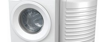
When buying a sewing machine, it is worth understanding that the shuttle installed in it depends on its cost:
- economy class appliances – vertical;
- middle class, cars with functions – horizontal;
- industrial or professional models used for intensive work - swinging.
If you read the reviews, users praise the type of shuttle mechanism they are used to working with. To purchase a suitable machine, take into account your own specialization:
- pendulum, rotational type is suitable for those who have little experience in sewing. Such machine models do not have a set of functions, but their shuttle is simple to use, reliable and durable. Equipment with such a system is taken for rare use;
- horizontal should be chosen by those who want to create a small number of things from different fabrics, without finding fault with the sewing speed. Sewing machines with such a mechanism have good functionality, and their price starts at 8,000 rubles;
- a rotating vertical mechanism is the choice of professionals and studio employees who value stitch selection, quality and comfort.
A “home” option when you want to sew for yourself is a horizontal shuttle. If you properly monitor the condition of your sewing machine, it will remain operational for a long time.
Vertical Rotating Sewing Hook
The vertical sewing hook or “double-fitting shuttle” is used mainly in the designs of industrial machines, but is also found in expensive household models of sewing machines. See vertical sewing machine hook.
From the old Soviet household sewing equipment, this type of shuttle is installed in the German Veritas sewing machine, although not all models. Many owners of these machines, without even knowing what type of shuttle the machine has, still use them perfectly, wondering how good the machine is. Of course, it's not just about the type of sewing hook, but it is nonetheless a deciding factor if you're going to be doing a lot of sewing on your machine and sometimes on rough, thick fabrics.
However, this does not mean at all that since this type of shuttle is available, you can sew a leather coat on a household sewing machine. The thickness of sewn fabrics allowed for a particular sewing machine model also depends on other important factors specified in the instructions. It’s not worth violating the manufacturer’s requirements, if only because the machine may have plastic gears and they will simply break due to increased load. See Repairing leather clothing at home.
Another advantage of a vertical sewing shuttle is that such a shuttle can be conveniently adjusted taking into account certain conditions for sewing fabrics. The interaction of the shuttle nose and the needle is adjusted quite simply and intuitively. This is a type of shuttle for professional use. It interacts very accurately with the needle, is reliable, vibration-free and allows the machine to work efficiently at high speeds.
How to properly thread the bobbin case.