Stereo headphones
(headphones) is a mobile sound-reproducing device designed for individual listening to music and speech.
According to their design, headphones are:
- Intracanal (droplets, plugs, barrels, vacuum bags, earplugs), which are inserted into the ear canal;
- Overheads that are inserted into the auricle;
- With a headband on which two phones are mounted;
- With a headband on which two phones and a microphone (headset) are installed.
In the vast majority of headphones, the sound signal to the phones and microphone is supplied through wires, chafing of which is the main cause of failure. If you wish, such headphone malfunctions can be easily fixed with your own hands, which is what will be discussed in the article.
Electrical circuit of headphones
To successfully repair any wired headphones, it is necessary to understand their structure, electrical circuit and wiring procedure.
The presented electrical diagram shows the wiring of headphone wires to jack (mini-jack) ⌀3.5 mm connectors that are widely used for transmitting audio signals.
Mini-jack 3.5 plugs are widely used for transmitting audio signals in headphones and microphones, sound cards of computers and tablets, cell phones, audio amplifiers and audio speakers.
Until 2012, the pinout of mini-jack 3.5 connectors was carried out according to the OMTP (Open Mobile Terminal Platform) standard. In the diagram these are jacks of the TS, TRS and TRRS OMTP types. Since 2012, a new CTIA (Cellular Telephone Industries Association) standard has been adopted, according to which all audio systems are currently soldered; in the diagram this is the TRRS CTIA jack (located on the right in the photo).
The polarity of the R+ and L+ channels is indicated conventionally, since the audio signal represents alternating current. But this is necessary for phasing the left and right channels. For a mono system, a single wire transmits an audio signal to two headphones connected in parallel. But the polarity of connecting the speakers must also be observed.
Mini-jack 3.5 interchangeability
When connecting headphones to the output of an audio device, you should take into account that, despite the same geometric dimensions, mini-jack 3.5 are not always interchangeable.
If you connect stereo headphones with a TRS, TRRS OMTP or TRRS CTIA plug to a jack intended for mono headphones with a TS plug, then only one left earphone will work.
When you connect mono headphones with a TS plug to the TRS, TRRS OMTP or TRRS CTIA connectors, both phones will work without a stereo effect. In simple headphones, phones are connected in parallel
The TRS plug is fully adapted to work with TRRS OMTP and TRRS CTIA connectors. But when using headphones with a microphone, called a headset, there may be problems.
Interchangeability of TRRS OMTP and TRRS CTIA
If a modern headset with a TRRS CTIA plug is connected to a device with a TRRS OMTP connector installed, the microphone will not work, and the headphones will distort greatly. This is due to the fact that the microphone input pin will be connected to the common wire, and the common to the microphone wire.
With this connection, the audio signal current can only flow through the circuit from the L+ terminal, through phones connected in series in antiphase and R+. The signal from the common wire will go to the microphone, but due to its high internal resistance it will not affect sound reproduction.
If you press the SB microphone lock button, the headphones will work normally. If there is no need for a microphone, then by locking the SB microphone lock button, the headphones can be used without harm to the equipment. But if you need a microphone or plan long-term use of the headset with the device, then you need to disassemble the headset and re-solder the GND and Mic wires.
A similar situation will be observed if the TRRS OMTP plug is inserted into the connector under the TRRS CTIA plug.
Color wiring of wires
The cord extending from the plug contains several wires of different colors. High-quality cables use tinsel-type stranded wire, in which thin wires are woven together with nylon or linen thread, which increases the mechanical strength of the wire for stretching and bending.
There is no international standard for wiring colors. Therefore, manufacturers solder wires to the jack terminals, guided by internal documentation.
But from practice we can conclude that the common GND wire is not painted by all manufacturers and has the color of copper coated with insulating varnish.
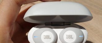
Deciding which wires to twist
There are clearly more wires in the headset than three - there are five of them. Two wires are for the microphone, and three for the headphones. A frayed gold wire (ground) was wound over a thin white wire - a microphone one.
Now we are faced with an impossible task - twisting the necessary wires together . actually simple ! Three AUX - wiring to three headphone wires. In this case, it turned out that the colors of the internal wiring coincided and by twisting the same colors the headphones started working.
To learn how to determine the colors of the necessary wires, read the article: Repairing a headset jack or five wires for four contacts
You can also use this simplest method: we plug our connector into any audio device that is at hand. The cassette player was closest to everyone.
Repair of in-ear headphones
Wired in-ear headphones are currently very popular. Low price, small size and acceptable sound quality make them indispensable for use in headsets for mobile devices.
Since headphones are used while moving, the wires are constantly bent and therefore fray over time, usually at the point of entry into the phones, less often at the jack.
The location of the wire break is usually obvious; the sound in one of the phones begins to periodically disappear when the wire moves. In this case, even without instruments, it is clear where the wire has frayed. Let me give you an example of self-repair of HTC in-ear headphones.
In these headphones, the wire at the input of one of the phones was frayed. To repair, you need to open the case. To do this, insert the knife blade into the gap between the body halves and, rotating slightly, separate the halves.
Typically, the halves of the phone are fastened together due to a tight fit, thanks to a groove in one part and a protruding collar in the other, so they separate without problems.
After disassembling the phone, it became clear that one of the pair of wires was broken, and part of the wires in the second wire were also broken. Taking into account the fact that the cord at the entrance to the headphone is also worn out, it is necessary to remove all of its unusable part.
Therefore, the conductors were sealed off from the phone, the cord was cut a couple of centimeters and the wires were stripped of insulation. Then the fixing bracket was released and removed and secured by crimping with pliers on the cord in a new place. The location was chosen on the basis that when the cord was pulled, the soldered conductors would not be stretched.
All that remains is to tin and solder, observing polarity, the wires to the headphone emitter. Pliers were used as a third hand. The handles of the pliers were equipped with a rubber band, which ensured easy clamping of the phone.
All that remains is to close the halves and check the headphones in operation. During the repair, I also resoldered the wires in the second earphone, since they would have failed in the near future.
Cleaning off the varnish
To strengthen thin copper wires, manufacturers intertwine them with nylon thread. And nylon, as you know, burns well. It is possible, by the way, that the varnish also burns. Therefore, for a split second we bring the end of the wire into the fire. It quickly flares up and lights up slightly. When 1-1.5 centimeters burns out, you need to blow on it, if it doesn’t go out on its own.
Varnish and nylon leave a small residue, which in most cases can be easily removed with a fingernail. As a result, we have undamaged wiring cleared of varnish.
The main thing is not to keep the wiring on fire for too long, because... they can simply burn and fall off ((Some may find the option with a knife more convenient.
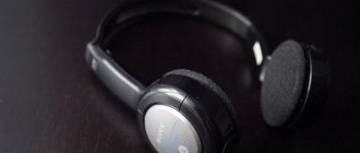
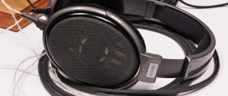
Repair of on-ear wireless bluetooth headphones
The sound signal to Bluetooth headphones is transmitted over the air. In this regard, there is no jack for connecting headphones to the signal source. Therefore, it is impossible to test the integrity of the cord wires using a multimeter.
A distinctive feature of this headphone model is the presence of permanent magnets on the back cover, which allow you to hold phones together. But this does not affect the repair technology, but it is convenient to use.
As a rule, both phones rarely fail at the same time; usually one of them starts to act up. It is more difficult to open the control unit, so troubleshooting must begin with the earphone that has stopped working.
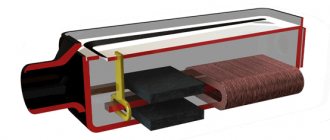
Typically, an earphone consists of two parts connected to each other by friction. To disassemble the earphone, you need to insert a knife blade into the gap between the halves of the housing and turn it.
After opening the earphone, the reason for its failure immediately became obvious. The copper-colored common conductor was broken.
The cord was pulled into the housing and cut along the line where it entered the earphone. Often, in headphones, the cord frays precisely at the entry point, therefore, in order to prevent possible damage in the near future, the cord was cut at this place.
The cord insulation was melted around the circumference using a soldering iron and removed. Here you must not overdo it, so as not to melt the nylon thread inside the tinsel conductors.
The wires are covered with a layer of varnish, which is destroyed when heated. Wires are well tinned with solder when using aspirin tablets as a flux. All that remains is to solder the conductors to the phone, observing the polarity.
The crimped brass brackets were very stiff and difficult to straighten. Additionally, they only secured the cord in the direction of exit of the earphone, but allowed the cord to enter it. As a result, the wire inside broke. To eliminate this, the cord was fixed with a drop of hot-melt adhesive. When you pull the cord into the hole in the headphones, the hot-melt adhesive will compress and firmly fix it.
At the same time, the cord of the second earphone was also soldered. If the wire frays in one, it will soon fray in the second. The photo shows cord trimmings left after the repair.
The DIY headphone repair is completed and now they will last even longer than they lasted before the repair, because the design flaw that caused the headphones to fail has been eliminated.
We isolate the wiring
Since we removed the varnish from the wires, they now have no insulation. If you close the twists together, you will either make yourself a mono or cut off one channel. Therefore, they need to be isolated to prevent short circuits between themselves.
First, we isolate each twist separately. In addition to the insulation itself, this will also strengthen the connections. For some reason I did this with masking tape, probably lying closer. It doesn't matter.
Now let's wrap everything together with wide tape, 3 - 4 layers. Or 5 - a matter of taste)
Usually in such cases I prefer to space the twists further apart so that they do not touch each other.
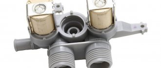
Repair of wired headphones with microphone CHP 510
With wired on-ear stereo headphones such as a headset, the wires in the cord usually fray at the point where they enter the phone.
A friend of mine brought me the headphones that you see in the photo with just such a problem. He repaired the headphones himself, soldering the broken wires with solder, but they broke again. This repair method only results in short-term operation of the headphones.
For a quality repair, you need to cut off the frayed cord, disassemble the earphone and solder the wires directly to the sound emitter.
You need to start disassembling the earphone by removing the ear pads. To do this, you need to pull it by the edge with your fingers and, using the blade of a flat-head screwdriver, remove it from engagement with the phone.
After removing the ear pads, four latches became visible. Sometimes the phone cover is secured with screws.
To remove the cover, you need to press the latches in the direction of the center one by one, using a flat-head screwdriver, and press them out.
After cutting off the frayed section of the cord, I was faced with the fact that it was tightly fused into the elastic tube protecting it from sharp bending. I had to remove the wires from the tube using a drill. After cleaning, the tube was put on the cord.
Next, very carefully, so as not to damage the wire strands, cut off the insulation with a knife. A soldering iron will not help here, since the conductors are practically fused into the insulation, and it was impossible to move it from the wires.
After removing the polyvinyl chloride insulation, the ends of the conductors must be tinned using a soldering iron and flux. The photo shows a cord prepared for wiring into the headphone.
In order not to get confused with the markings, faulty wires were not unsoldered in advance, and at the time of soldering new ones, the old one was unsoldered and soldered in its place of the same color.
The wires going to the speaker of the opened earphone were soldered directly to its terminals. Those going to the second earphone and microphone were connected by soldering wires to each other. For insulation, existing paper tape covered with a sticky layer was used.
The photo shows self-repaired CHP 510 headphones, which I hope will last for many more years
Improving technology:
Still, using tape is not kosher. Therefore, I propose to improve the technology a little, again without a soldering iron.
You will have to buy a heat-shrinkable tube, also known as thermal casing, at an electronics store or hardware store. This is such a clever tube that can shrink in diameter by at least half when heated. This miracle costs about $0.1 - $0.5 per meter.
We will need two thermal casings with diameters of 1-2 mm and the second 4-5 mm. We put pieces of thin thermal tube on our twists. We cut the pieces with one and a half margin.
Now you need to heat up the thermal chamber. Usually I did this with a soldering iron, but... We agreed that I didn’t have one, and the story was about how to fix headphones without a soldering iron, I had to get out of it.
The method turned out to be quite effective and the heat tubes shrank. You can use a halogen or iron. In principle, people use a regular hairdryer to warm them up. Usually, while they are still hot, I additionally flatten them with my fingers because... It’s not always possible to have tubes of the required diameter on hand, and even then they stick together slightly inside.
Before twisting the wires, you must remember to put a 4 mm thermal tube on the headphone wire. This heat tube must subsequently be put on the joint and also compressed with the heat of the lamp. In general, you can squeeze lighters over a fire, but you can accidentally melt or set fire to excess.
I used a piece about 8 or even 10 cm long. To strengthen it, the end of the thermal tube was put directly on the rubber band of the connector.
The view has clearly changed for the better
As you can see, this is not as difficult as it seems and now you know how to fix headphones without a soldering iron. Such a repair cannot be called complete; it is rather an alternative for emergencies.
Of course, it is possible that your headphones will work for a long time after such repairs. In any case, it will be safer to solder twisted headphone wires. This is not at all difficult to do. Read how: How to easily learn how to solder correctly using headphones as an example
- Samodelkin April 30, 2013
- Computer homemade products and sound tuning
In this article I will tell you how to repair headphones or a headset for a computer or mobile phone yourself. We will look at the main breakdowns and how to fix them.
Repair of headphones with headband and microphone Genius
Genius headphones were repaired because the wires were frayed and the phone mounts to the headband were broken.
The headphones were brought to me for spare parts, but after assessing their technical condition, I came to the conclusion that they could be repaired.
Repair of headphone-to-headband attachment
Before repairing the frayed wires, it was first necessary to repair the mechanical damage to the attachment points of the headphones to the headband.
An opening of the components showed that the protrusions used to fix the flat spring of the headband were missing. It looks like the headphones were dropped and the flat spring simply cut them off.
It was possible to secure the spring in the assembly using two screws, but for reliability I decided to use a combined type of fastening - one screw and hot-melt adhesive. To do this, first a hole was drilled in one of the halves and an M3 screw was inserted into it.
Next, the pieces of hot-melt glue were melted with an electric soldering iron, and while the glue was still hot and hardened, the headband spring was installed and the nut was screwed onto the screw. The second unit was repaired in the same way.
The thickness of the plastic of the assembly allowed the use of a screw with a conical head, which was fused into the drilled hole using a soldering iron. If desired, the screw head can be coated with black varnish.
As you can see in the photo, the appearance of the headphones has not changed. The ability to adjust the length of the headband remains. Now the headphones are securely attached to the headband, and you can begin repairing the cord.
Headphone cable repair
The multimeter did not dial through the headphones through the jack, so I had to disassemble the phones. Disassembly begins with removing the ear pads from the phones.
To do this, grab the edge of the ear pad and pull it back with your hand. Next, pry up the ear pad using a screwdriver and carefully remove it from engagement with the headphone body in a circle.
To disassemble the earphone, just unscrew three screws and the cover will come off. But one of the screws rotated, but did not come out.
It turned out that one of the threaded posts had broken off. I had to use hot glue to install a metal stand with internal threads instead.
A volume control and microphone mute control unit is installed on the headphone wire. To determine with a multimeter where the wires were broken, we had to disassemble the unit. To do this, it was enough to unscrew two self-tapping screws.
A test with a multimeter showed that the speakers in the headphones were working properly and had a resistance of 31 ohms. And the wires in the cord had a break both in the jack section - the volume control, and from the volume control to the headphones. I had to cut off a section of the cord, both at the headphone and on both sides of the volume control, and resolder the wires.
The movement of the cord in the headphone body was limited by tying it in a knot. This is a bad option because the cord has the ability to move inward and rotate, which could result in the wires breaking.
Therefore, the cord was secured with hot glue. First, glue was applied to the cord, which was pulled into the sleeve until the glue hardened. Then the cord was fixed to the earphone cover with hot glue.
All that remains is to solder the wires according to the color markings, twist the earphone halves and put on the ear pad.
Now it's time to repair the sound control unit and turn off the microphone. In this model of headphones, to open the unit, it was enough to unscrew two screws.
The cords in the block were fixed using plastic bushings, which could not be removed from the cord. Therefore, the bushings were cut lengthwise with a knife.
Next, sections of the cord were cut off and the insulation was removed using a soldering iron. It is worth noting that the wires through which the sound signal was supplied to the headphones and the microphone were, to reduce mutual influence, isolated from each other.
To fix the sleeve on the cord, a drop of hot-melt adhesive was applied to it; you can also apply instant glue. But hot melt glue hardens faster.
Next, until the hot-melt glue hardened, the sleeve was pushed onto the hot-melt glue and compressed using a wrap of thread.
All that remains is to solder the wires to the contact tracks of the printed circuit board and assemble the adjustment unit. To make it easier to solder, I pressed the board with pliers. At the same time, the volume control was also lubricated with machine oil.
Do-it-yourself repair of Genius headphones with a microphone is completed. The check showed their proper operation. Now the headset, if handled carefully, will last for many years.
Now let's remove the rubber braid
Especially for this article, the dumbest knife was found in order to try everything for myself).
It is most convenient to cut the braid exactly as in the photo. You don't need to press the blade too hard. Thanks to bending, the braid itself will diverge. We turn the wire, making cuts and, when we have gone through the circle, remove the braid. The main thing is not to cut through the wiring.
It’s better to expose about 2 centimeters of the wiring, it will be easier and the contact area will be larger. Which will increase reliability. The wiring is covered with varnish that needs to be cleaned off. First there was an attempt to clean the varnish with a knife.
Not the best way. The wires are very thin and with such rough mechanical action they come off along with the varnish. The dullness of the knife contributes well to this. In principle, this can be done easily with a sharp knife. But we don’t have a sharp knife, so we’ll use a lighter. Well, or at least matches.
Repair of Panasonic RP-WF83 wireless headphones
I had to repair Panasonic RP-WF83 wireless headphones, which worked fine, but the batteries located in the headphone from the base did not charge.
We had to take them out and charge them from a separate charger, which created inconvenience.
In one of the recesses of the base with the transmitter there were two spring-loaded contacts, through which the charge current was transmitted to one of the headphones. Measuring the voltage on these contacts with a multimeter turned on in constant voltage measurement mode showed that the charger circuit in the base is working.
Therefore, the fault is in the earphone itself. To get to the electronics, you need to remove the ear pad and unscrew the screws, as described in the article above. Upon inspection of the board, the reason for the failure immediately became clear.
The printed traces to which the contacts were soldered to connect to the base were torn off from the board. Considering that only the pressure of the moving contacts of the base was applied to them, the failure occurred due to a design flaw. The contacts were sealed in such a way that when pressure was applied to them, the force was transferred to tearing off the tracks.
The torn off printed pads were glued to the board with Super-Moment glue. Next, as shown in the photo, they are covered with a layer of solder.
Two thrust angles were made from a brass plate, tinned with solder and soldered on the inside of the contacts. The corners can be made from any metal, iron is also suitable, the main thing is that the metal is tinned with solder.
Now all the pressure will be applied not to the place where the contacts are soldered to the printed circuit board, but to the installed corners.
The cracked tracks were simply tinned and covered with a thick layer of solder. If the track is badly damaged, you can duplicate it with copper wiring.
To check the charging of the batteries, wires were connected to the contacts and connected to a voltmeter, which showed a voltage of 2.61 V. This indicated that the batteries were charging, since their operating voltage cannot exceed 2.5 V.
The practice of using the headphones has shown a stable battery charge. Do-it-yourself repair of wireless headphones is completed and now they will never again fail to work due to broken contacts.
Other problems with wireless headphones
Wireless headphones, due to the lack of a cord, rarely break down. They usually stop working if the batteries or accumulators are dead. It also happens that the battery contacts oxidize, in which case they need to be washed with alcohol, or maybe with vodka.
If the switch on the headphone becomes unstable, you need to wash it by dropping a drop of alcohol inside and turn it on and off several times. If it doesn't help, you'll have to replace it with a working one.
If wheezing appears when adjusting the volume or the sound is interrupted, then also first drop a drop of alcohol into its interior and, after turning the wheel several times, add a drop of machine oil.
Donor needed
Unfortunately, you won’t be able to solder the headphones without a soldering iron. Of course, if you wish, you can solder with a hot nail. But to do this you already need to know how to solder. Yes, and tin and rosin will still be needed...
The only difficulty that may arise along the way is that you will need a known working AUX cable or connector from other working headphones with a piece of wire.
An AUX cable is cheaper to purchase than headphones, but it does not have a microphone, so if you have a headset, you will have to come to terms with the fact that it will be reduced in powers and will lose a microphone and buttons. But how nice it is when headphones that aren’t working start singing, and you can survive the lack of buttons.
AUX cable is now sold in any stall or passage for absolutely ridiculous money. It is usually needed to connect your audio device (phone, player...) to a subwoofer or car radio.
Thanks to the Chinese brothers, now there are quite tolerable laces starting from $0.5 . The wire used in the article cost about a dollar. Well, I think every house has a paper knife, a lighter and some scotch tape lying around in closets.
So we scraped through the bottom of the barrel, well, in the sense of the cabinets, found all the tools, drove them to the stall for ( beer)
string, what's next?