History of creation
The method of transferring dry dye to paper was patented in 1938 by US inventor and physicist Chester Carlson. The method was based on the use of static electrical energy. The technology was adopted by Xerox 10 years later. It took another 10 years to refine the electrographic transfer method and to invent a device that could automatically display information on paper. At first the machine was cumbersome and some operations had to be done manually. Only in the 50s. A fully automated mechanism was created, which is the prototype of modern laser printing technology.
The laser beam was added to the printer design by Xerox in 1969, and the first printer went on sale in 1977. It was the Xerox 9700 model. Only large companies and offices could buy the innovative device, since the price exceeded 300 thousand. The speed of the first printing technology was 120 pages per minute, it could do double-sided printing. Printers became available to ordinary private users after 5 years. They were started to be produced by Canon. Then the number of manufacturers and new models of printing equipment increased rapidly every year.
Heat fixation print
Without fixing the applied coloring composition, a full print cannot be obtained. Laser printer toner is so fine that it even has flowing properties.
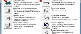
The text or design is fixed using a thermal element that bakes the paint onto the media. The printer's heater is located on the path where the printed sheet exits the path. Structurally, the heating unit consists of two elements:
- thermal roller;
- pressure shaft.
Depending on the manufacturer, the heating roller material and temperature conditions may vary. Heating is no more than 250 °C, and the material can be Teflon or thermal film.
Fig.4 Laser printer fuser
The Teflon construction is more durable, and heating is carried out by a lamp placed inside the structure. Cooling is not provided; the temperature rise is monitored by a thermistor, which turns off the heating source if the permissible values are exceeded.
The main problems with such a stove may be its contamination or failure of the temperature sensors and lamp. But, without this irreplaceable section involved in printing, high-quality prints cannot be obtained. Cleaning Teflon from toner residues is done with a special felt roller. But this part does not help during long-term operation of the printer and additional cleaning of the unit from time to time is recommended.
More common in the design of a thermal roller is the use of thermal film. It is made of elastic, heat-resistant plastic, and is installed in budget devices. Heating is produced by a ceramic element located inside the shaft.
Thermal film is more susceptible to traumatic effects, especially if not handled carefully. Using sheets for secondary printing without freeing them from staples is a fairly common situation. The price of the film and the cost of repairs are affordable and carried out in a short time.
In addition to the listed blocks, which are responsible for the most important procedures in the operation of the printer, there are many more connecting parts and additional working links. All this is also subject to changes during the operation of printers.
Table
Common malfunctions of laser printers
| Problem | What could be wrong |
| Not the entire image was pinned. There are creaks inside the device. There is a paper jam at the exit. | Fuser (furnace) |
| White stripes along the leaf. Print density is low. | Laser unit |
| The paper jams before reaching the fuser roller. | Paper conveyor |
| Pale print. | Toner Transfer Roller |
| The printer does not turn on. | Interface board |
Our technicians are always happy to support you in your efforts to extend the life of your laser printer.
20358
Tags for this article
Expert Reviews
Comments
Laser printer device
A laser printer is a printing device that applies toner to media using photoelectric xerography.
Different models may have minor differences, but the basic operating elements will be the same.
- Scanning mechanism. It consists of rotating lenses and mirrors. By correctly arranging them, the required image is formed on the surface of the photodrum, which is applied with a laser. Since the picture is not applied with dye, but simply changes the charge of particles on the surface of the shaft, it cannot be seen. A controller with a raster processor is responsible for the operation of the scanner.
- Block for transferring an image to a medium. It includes a cartridge and a charge transfer roller. The cartridge consists of a photo shaft, a charging and a magnetic shaft. It is on the surface of the photo roller of the cartridge that the charge changes under the influence of the laser. The transfer roller, using a neutralizer, removes static charge from paper entering the printer. This is to prevent the sheet from sticking to the drum.
- Unit for final fixation of the image on the media. After the toner is transferred to the sheet, it passes through an oven, where it is “baked” under high temperature. The particles contained in the toner easily melt and reliably fix the print on the paper, so the applied pattern is not erased and is well preserved for a long time.
- Interface block. Responsible for the exchange of information and interaction between different nodes in the printer.
- Printers from Xerox, Canon, and HP brands use positively charged toner. Therefore, the laser draws an image with a negative charge, which attracts the powder to the surface of the drum. This technology allows you to draw the image on the media as much as possible.
- The operating principle of laser printers from Brother, Kyocera, Epson is different, since their toner has a negative charge. The laser changes the charge not of those areas on which the image should be applied, but, on the contrary, of the spaces between the drawn elements. This method distributes the toner evenly over the surface of the sheet.
Development
Magnetic shaft
Another shaft available in the cartridge, magnetic (Magnetic Developer Roller), is a metal tube with a magnetic core inside. The shaft is located so that part of its surface is practically in the refill hopper with toner and closes it like a lid. Inside the compartment, a magnet attracts the powder to the surface of the Magnetic Roller, and, rotating, carries the toner out.
To regulate the thickness of the powder layer and prevent its uneven distribution on the roller surface, a metering blade (Doctor Blade, Metering Blade) is used. The metal frame of the doctor is attached rigidly, leaving a gap between the flexible plate on the edge of the dosing blade and the shaft of a certain size. Thus, only a thin layer of powder is passed through, and all excess is dumped back into the compartment. An improperly installed Doctor Blade - a wide or uneven slot - can cause excessive toner spillage and black streaks on the printed page.
Dosing blade
Next, the toner falls between the magnetic roller and the OPC, where in the exposed areas it is attracted to the surface of the drum, and in the charged areas it is repelled. The powder remaining on the Mag Roller moves on and passes through the hopper again, where a new portion of ink is attracted to the areas of the magnetic roller freed from toner and the cycle is repeated. And the toner, which has moved to the photodrum, makes the image on it visible, and follows to the paper medium.
Cartridge device
A simple cartridge consists of a dye compartment, a waste compartment and a photo roller. The drum cartridge contains a photocell and toner.
Toner is a fine black powder. The color machine uses violet, yellow and blue dye. The powder consists of polymer particles coated with a dye containing magnetite and a charge regulator. From different manufacturers, the powder differs in grain size, magnetization and dispersion, so you need to refill the cartridge only with the toner that is intended for a specific model.
The appearance of the cartridge in different models may be different, but they all consist of the following elements:
- The toner compartment where it is stored.
- Magnetic shaft. Through it, the powder is fed from the hopper to the photocell.
- Dosing blade. Responsible for the thickness of the toner layer that falls on the surface of the photo roll.
- Raquel. After transferring the paint from the photo roll to the paper, the squeegee cleans the surface of the roll from powder residues.
- Charge roller. Charges the drum surface.
- Compartment for working out. Waste toner gets into it.
Some cartridges have a built-in microchip that collects information about the number of pages printed. If necessary, it can be replaced.
Also, during operation, other parts of the cartridge, which are considered consumables, may wear out. The cartridges themselves can be refilled many times and used until the gears or body parts are completely worn out.
Cartridge design
Consumable material for laser printing - toner - is located in the cartridge. An ordinary device consists of three main compartments, where the dye, waste and photo roll are located. Powdered grains are most often used as toner. Black and white models have only one container.
Dyes differ in the quality of the composition - the degree of magnetization and dispersion, as well as grain size. Therefore, there are no universal toners as such. As a rule, manufacturing technicians try to adapt the needs of an entire line of printers to a single dye, rather than making each model original.
The dimensions of the cartridge can be very different and depend on the specific printer. Low-impact household models are equipped with modest-sized containers, while professional equipment comes with massive, sometimes even double or triple blocks. But the design features of the devices are approximately the same.
Main elements of a laser cartridge:
- The toner compartment contains the dye powder.
- A movable shaft that supplies toner to the photocell.
- A dispenser that regulates the volume of dye for the drum.
- A squeegee that clears the surface of used toner to apply a new layer.
- Magnetic roller that charges the photo roller.
- Waste toner compartment.
Some printers are equipped with chip cartridges, which allows you to track the number of printed sheets, ink remaining and other information. All data is reflected in the manufacturer’s proprietary application, which is installed along with the drivers.
Cartridges can be refilled several times, and individual elements (rollers, gears, shafts) can be replaced if necessary. With rare exceptions, one-time solutions can be found. But the practicality of purchasing such devices is questionable.
How a laser printer works: printing principle
Drum charge
A sensitive green or blue layer is applied to the surface of the photo roll. In some models, the charge transferred to the photodrum will be positive, while in others it will be negative.
Charging occurs in two ways.
- A special tungsten filament with a carbon coating and gold/platinum particles is supplied with high voltage, under the influence of which a magnetic field is created. During the laser printing process, the filament often becomes contaminated, which reduces the quality of the printed image.
- Instead of a tungsten filament, a charge roller is used. Externally, it looks like a metal cylinder coated with a conductive substance (special rubber, foam rubber). When the image drum touches the roller, a charge is transferred. The roller does not get dirty as quickly as the thread, but its service life is much shorter.
Creating an Image (Exposure)
During exposure, an invisible image is formed on the photodrum, which is an exact copy of the image sent by the user for printing. Depending on the printer model, the pattern will be formed in areas with a negative or positive charge. The charge is replaced by a laser beam striking first the mirror and then the lens.
The first line is formed when the laser is turned on/off. Then the drum is rotated and a new part of the image is applied. This takes a split second. The remaining toner is cut off with a squeegee and dumped into the waste compartment.
Development
At this stage of the printer’s working circuit, the main element is the magnetic shaft. It looks like a metal hollow cylinder with a magnetic core inside. The magnetic roller fits tightly to the photo roller and toner compartment. When the shaft rotates, a magnetic core located inside attracts toner to the surface of the shaft and is simultaneously applied to the photocell. In places where the charges of the dye and the surface do not match, toner particles “stick” occurs.
Transfer to paper
The stage involves a transfer roller. The metal base can change the charge and transfer it to the paper sheets. The principle of transferring toner from the photodrum to paper is the same as from the magnetic roller. The dye is held on the surface due to static tension; without it, it would scatter across the page.
Pin an image
The toner contains components that melt under high temperatures. To fix the design on paper, the sheet passes through a stove inside the machine. It consists of two shafts, the top of which contains a heating element, and the bottom serves as a press that pushes the paper for more reliable fixation.
The thermocouple of the stove heats up to 200 °C and bakes the dye.
Cheap printers use thermal film, while more expensive ones use Teflon and lamps. The advantage of such models is the increased service life of the toner fixing mechanism.
The process of creating an impression
The appearance of an image or text on paper will consist of the following successive stages:
- drum charge;
- exposure;
- development;
- transfer;
- consolidation
Drum charge
How does photo charging work? It is formed on the photodrum (where, as is already clear, the future image itself is born). To begin with, a charge is supplied, which can be either negative or positive. This happens in one of the following ways.
- A corona wire is used, that is, a tungsten filament coated with carbon, gold and platinum inclusions. When high voltage comes into play, a discharge is carried between this thread and the frame, which, accordingly, creates an electric field that transfers charge to the photodrum.
- However, the use of filament led to problems with contamination and deterioration of the printed material over time. A charge roller with similar functions works much better. It itself looks like a metal shaft, which is covered with conductive rubber or foam rubber. There is contact with the photocylinder - at this moment the roller transfers the charge. The voltage here is much lower, but the parts wear out much faster.
Exhibition
This is the work of illumination, as a result of which part of the photocylinder becomes conductive and passes a charge through the metal base in the drum. And the exposed area becomes uncharged (or acquires a weak charge). At this stage, a still invisible image is formed.
Technically it works like this.
- The laser beam falls on the surface of the mirror and is reflected onto the lens, which distributes it to the desired location on the drum.
- This is how a system of lenses and mirrors forms a line along the photo cylinder - the laser is turned on and off, the charge either remains intact or is removed.
- Has the line ended? The image drum will rotate and exposure will continue again.
Development
In this process, the magnetic shaft from the cartridge is of great importance, similar to a metal tube, inside of which there is a magnetic core. Part of the roller surface is placed in the refill toner hopper. The magnet attracts the powder to the shaft and it is carried out.
It is important to regulate the uniform distribution of the powder layer - for this there is a special dosing blade . It allows only a thin layer of toner to pass through, throwing the rest back. If the blade is not installed correctly, black streaks may appear on the paper.
After this, the toner moves to the area between the magnetic roller and the photo cylinder - here it will be attracted to the exposed areas and repelled from the charged ones. This way the image becomes more visible.
Transfer
In order for the image to appear on paper, a transfer roller comes into play, the metal core of which attracts a positive charge - it is transferred to the paper thanks to a special rubberized coating.
So, the particles come off the drum and begin to move onto the page. But they are held here so far only due to static tension. Figuratively speaking, the toner is simply poured where needed.
Dust and paper lint may get in with the toner, but they are removed by a wiper (special plate) and sent straight to the waste compartment on the hopper. After a full circle of the drum, the process is repeated.
Pin an image
To do this, the property of toner to melt at high temperatures is used. Structurally, the following two shafts help with this:
- there is a heating element in the top;
- at the bottom, melted toner is pressed into the paper.
Sometimes such a “stove” is a thermal film - a special flexible and heat-resistant material with a heating component and a pressure roller. Its heating is controlled by a sensor. Just at the moment of passage between the film and the pressing part, the paper heats up to 200 degrees, which allows it to easily absorb the toner that has become liquid.
Further cooling occurs naturally - laser printers usually do not require the installation of an additional cooling system. However, here a special cleaner passes through again - usually a felt roll plays its role.
Felt is usually impregnated with a special compound, which helps lubricate the coating. Therefore, another name for such a shaft is oil.
How does a color printer work?
Color machines contain 4 cartridges with black, blue, violet and yellow toner. In expensive devices, the number of capacities may be greater.
The printing principle of a color printer does not differ significantly from the operation of a monochrome printer. The only difference is that the application of dye to obtain a color image is done separately by each cartridge. Depending on the number of passes, there are single-pass and multi-pass devices.
The multi-pass type has a special shaft or belt. One color is applied per revolution of the drum. The number of revolutions is equal to the number of colors used, due to this the total time of applying the image to the paper increases. In a single-pass device, the image is drawn with all colors at once. To achieve this, each cartridge is equipped with its own laser system and portable roller. This type of printer prints faster than a multi-pass printer, but is more expensive.
A color laser printer has its advantages and disadvantages. Compared to an inkjet, it prints faster, but the quality of the resulting image will be slightly lower due to the fact that dry ink conveys tones worse. This color rendering is sufficient for printing graphs and diagrams, which is why color printers are bought mainly for offices. It is purchased less often for the home due to the high cost of both the device itself and maintenance.
Color print
Four primary colors are used to form a color image:
- black,
- yellow,
- purple,
- blue.
Printing is carried out on the same principle as black and white, but first the printer splits the image that needs to be obtained into monochrome images for each color. During operation, color cartridges transfer their designs onto paper, and their superimposition on each other gives the final result. There are two color printing technologies.
Multipass
Brother HL-4050CDN printer
This method uses an intermediate carrier - a roller or toner transfer ribbon. In one revolution, one of the colors is applied to the tape, then another cartridge is fed to the desired location and the second is superimposed on top of the first image. In four passes, a complete image is formed on the intermediate medium and transferred to paper. The printing speed of color images in printers using this technology is four times slower than monochrome.
Single pass
The printer includes a complex of four separate printing mechanisms under common control. The color and black cartridges are lined up, each with a separate laser unit and transfer roller, and the paper runs under the drums, sequentially collecting all four monochrome images. Only after this does the sheet go into the oven, where the toner is fixed on the paper.
Single pass printing
Have fun typing.
Popular representatives
- Xerox Phaser 3020BI. Black and white device for home and small offices. Practical and easy to maintain model. The cartridge can be easily replaced independently. There is a built-in wireless module that allows you to connect the printer via Wi-Fi. The printing speed of a page with text is 20 sheets per minute, photographs are printed 3 times longer. Even very small font prints legibly. Disadvantages - can withstand only light loads, takes a long time to warm up, the cartridge has a short lifespan.
- Kyocera FS-9530DN. High-speed monochrome device for medium and large businesses. It has several options for feeding paper with cassettes of different sizes. The developers provide the possibility of installing an additional device for stitching booklets and an automatic hole punch. The toner is not stored in a cartridge, but in a special container. One charge is enough to print 40 thousand A4 pages in normal mode and 100 thousand A4 pages in economical mode.
- Canon i-SENSYS LBP621Cw. Color printer for home and small offices. There is a module for wireless connection, direct and cloud printing is available. The printer heats up quickly and has a 250-sheet tray. There is no duplex printing and refills are expensive.
- Xerox Phaser. Compact color LED printer. It has high quality printing, but the price of original consumables may be higher than the cost of the printer itself. It connects easily, but prints quite slowly.
- HP Color LaserJet Professional CP5225 (CE710A). Large format color printing machine for medium and large businesses. As standard, it is connected only via a USB cable, but you can optionally install a wireless printing module. It is inexpensive, low cost of printing one page, but you cannot make double-sided prints.
5 / 5 ( 1 voice )
Types of laser toner
The term “toner” refers to a fine powder used in laser printers and electrographic copiers. This is a multicomponent substance with a complex composition. The service life of the cartridge directly depends on the quality of the toner. Therefore, if you have to deal with refilling a cartridge, you need to have an idea of the types of this consumable.
What does toner consist of?
Simplified toner classification
| Sign | Types of toner |
| Receiving technology |
|
| Magnetic properties |
|
| Color |
|
| Charge |
|
| Type of polymer included |
|
Since there are many types of laser printing, the above features can occur in different combinations. In addition, the same toner affects image quality differently in different printer models.
Combinations of toner and drum charges in various printing systems
| Printing systems | Toner charge | Drum charge | Examples |
| digital printing system | negative | negative | HP, Canon, Sharp, Ricoh, Samsung, Lexmark, etc. |
| digital printing system | positive | positive | Kyocera, Brother, etc. |
| analog printing system | positive | negative | Canon, Xerox, Sharp, etc. |
| analog printing system | negative | positive | Kyocera Mita |
Device types
How to use the printer? The first problem that users face is choosing a printing device.
Today you can find:
- laser printers;
- inkjet models.
In addition, all mentioned devices are divided into:
- black and white;
- colored.
Users decide for themselves which printers are right for them. Now color printers are popular, but black and white devices still do not remain in the shadows. There are such devices in almost every home. They are used to print black and white documents.
WORLD OF PC PERIPHERALS
Color laser printers are beginning to actively conquer the printing market. If just a few years ago color laser printing was something unattainable for most organizations, and even more so for individual citizens, now a very wide range of users can afford to buy a color laser printer. The rapidly growing fleet of color laser printers is leading to growing interest in them from technical support services.
Principles of color printing
In printers, as in printing, a subtractive color model is used to create color images, and not an additive one, as in monitors and scanners, in which any color and shade is obtained by mixing three primary colors - R (red), G (green), B ( blue). The subtractive color separation model is so called because in order to form any shade, it is necessary to subtract “extra” components from the white color. In printing devices, to obtain any shade, the following primary colors are used: Cyan (cyan, turquoise), Magenta (magenta), Yellow (yellow). This color model is called CMY after the first letters of the primary colors.
In the subtractive model, when two or more colors are mixed, complementary colors are created by absorbing some light waves and reflecting others. Blue paint, for example, absorbs red and reflects green and blue; purple paint absorbs green and reflects red and blue; and yellow paint absorbs blue and reflects red and green. By mixing the main components of the subtractive model, different colors can be obtained, which are described below:
Blue + Yellow = Green
Magenta + Yellow = Red
Magenta + Cyan = Blue
Magenta + Cyan + Yellow = Black
It is worth noting that to obtain black it is necessary to mix all three components, i.e. cyan, magenta and yellow, but getting high-quality black in this way is almost impossible. The resulting color will not be black, but rather a dirty gray. To eliminate this drawback, one more color is added to the three main colors - black. This extended color model is called CMYK ( C yan- M agenta- Y ellow-blac K - cyan-magenta-yellow-black). The introduction of black color can significantly improve the quality of color rendering.
HP Color LaserJet 8500 Printer
After we have discussed the general principles of the construction and operation of color laser printers, it is worth familiarizing yourself in more detail with their structure, mechanisms, modules and blocks. This is best done using the example of a printer. As an example, let's take the Hewlett-Packard Color LaserJet 8500 printer.
Its main characteristics are: - resolution: 600 DPI; — printing speed in “color” mode: 6 ppm; — printing speed in “black and white” mode: 24 ppm.
The main components of the printer and their relative positions are shown in Fig. 5.
Next, let's look at how images are created in this printer. Its imaging system is shown in Fig. 6.
Image formation begins with residual potentials being removed (neutralized) from the surface of the photodrum. This is done so that the subsequent charge of the photodrum is more uniform, i.e. Before charging it is completely discharged. Removal of residual potentials is carried out by illuminating the entire surface of the drum with a special preliminary (conditioning) exposure lamp, which is a line of LEDs (Fig. 7).
Next, a high-voltage (up to -600V) negative potential is created on the surface of the photodrum. The drum is charged with a corotron in the form of a roller made of conductive rubber (Fig. 8). The corotron is supplied with a sinusoidal alternating voltage with a negative DC component. The alternating component (AC) ensures uniform distribution of charges on the surface, and the constant component (DC) charges the drum. The DC level can be adjusted by changing the print density (toner density), which is done using the printer driver or through adjustments through the control panel. An increase in negative potential leads to a decrease in density, i.e. to a lighter image, while decreasing the potential – on the contrary, to a denser (darker) image. The photodrum (its internal metal base) must be “grounded”.
After all this, a laser beam creates an image on the surface of the photodrum in the form of charged and uncharged areas. The laser light beam, hitting the surface of the drum, discharges this area. The laser illuminates those areas of the drum where the toner should be. Those areas that should be white are not illuminated by the laser, and a high negative potential remains on them. The laser beam moves across the surface of the drum using a rotating hexagonal mirror located in the laser assembly. The image on the drum is called a latent electrographic image, because it is represented as invisible electrostatic potentials.
The latent electrographic image becomes visible after passing through the developing unit. The black toner developing module is stationary and is in constant contact with the photodrum (Fig. 9).
The color developing module is a carousel mechanism with alternate supply of “color” cartridges to the surface of the drum (Fig. 10). Black toner powder is single-component magnetic, while colored toner powders are single-component but non-magnetic. Any toner powder is charged to a negative potential due to friction against the surface of the developing roller and the dosing squeegee. Due to the potential difference and the Coulomb interaction of charges, negatively charged toner particles are attracted to those areas of the photodrum that are discharged by the laser and are repelled from areas with a high negative potential, i.e. from those that were not illuminated by the laser. At any given time, only one color of toner is developed. During development, a bias voltage is applied to the developing roller, which causes toner to transfer from the developing roller to the drum. This voltage is a rectangular alternating voltage with a negative DC component. The DC level can be adjusted as the toner density changes. After the development process is completed, the image on the drum becomes visible and must be transferred to the transfer drum.
Therefore, the next step in creating an image is to transfer the developed image to the transfer drum. This stage is called the primary transfer stage. The transfer of toner from one drum to another occurs due to an electrostatic potential difference, i.e. Negatively charged toner particles should be attracted to the positive potential on the surface of the transfer drum. To do this, a positive DC bias voltage is applied to the surface of the transfer drum from a special power source, resulting in the entire surface of this drum having a positive potential. When printing full color, the bias voltage on the transfer drum must constantly increase because After each pass, the amount of negatively charged toner on the drum increases. And in order for the toner to transfer and lay on top of the existing toner, the transfer voltage increases with each new color. This imaging stage is shown in Fig. 11.
During the transfer of toner to the transfer drum, some particles of toner may remain on the surface of the image drum and must be removed to avoid distorting the subsequent image. To remove residual toner, the printer has a drum cleaning unit (see Figure 17). This module contains a special shaft - a brush for removing the charge from the toner and the photodrum - this weakens the force of attraction of the toner to the photodrum. There is also a traditional cleaning squeegee that scrapes the toner into a special hopper where it is stored until the cleaning module is replaced or cleaned.
Next, the photodrum is charged again (after preliminary discharge), and the process is repeated until the image of the corresponding color is completely formed on the transfer drum. Therefore, the size of the transfer drum must fully correspond to the print format, i.e. in this printer model, the circumference of this drum corresponds to the length of an A3 sheet (420 mm). After applying toner of one color, the image formation process is completely repeated with the only difference being that a developing unit of a different color is used. To use another developing unit, the carousel mechanism rotates at a given angle and brings the “new” developing shaft to the surface of the photodrum. Thus, when forming a full-color image consisting of four color components, the transfer drum is rotated four times, and at each rotation a toner of a different color is added to the existing toner. In this case, yellow powder is applied first, then purple, then blue, and black powder is applied last. As a result, a full-color visible image is created on the transfer drum, consisting of particles of four multi-colored toner powders.
After the toner powder lands on the surface of the transfer drum, it passes through the additional charge unit. This block (Fig. 12) is a wire coroton, to which a sinusoidal alternating voltage (AC) with a negative direct component (DC) is supplied. With this voltage, the toner powder is additionally charged, i.e. its negative potential becomes higher, which will contribute to more efficient transfer of toner to paper. In addition, the additional voltage reduces the positive potential of the transfer drum, which helps ensure that the toner is positioned correctly on the transfer drum and prevents the toner from moving. The result is accurate reproduction of color shades. The additional charge voltage is supplied to the transfer drum during the application of yellow toner, i.e. at the very beginning of the image formation process. When applying yellow toner powder, the additional charge voltage is set to a minimum value, and after applying each new color, this voltage increases. The maximum boost voltage is applied while black toner is being applied.
Next, the full-color visible image from the transfer drum must be transferred to paper. This transfer process is called secondary transfer. Secondary transfer is carried out by another corotron, made in the form of a transport belt (Fig. 13). The toner is moved onto the paper by electrostatic forces, i.e. due to the potential difference between the toner powder (negative) and the secondary transfer corotron, to which a positive bias voltage is applied. Since secondary transfer occurs only after four rotations of the transfer drum, the corotron transfer belt must feed the paper only when all colors have been applied, i.e. during the fourth revolution, and until this point in time, the belt should be in such a position that the paper does not touch the transfer drum.
Thus, during image creation, the transport belt is lowered down and does not come into contact with the transfer drum, but at the time of secondary transfer it is raised up and touches this drum. The corotron transport belt is moved by an eccentric cam, which is driven by an electric clutch upon command from the microcontroller (Fig. 14).
During secondary transfer, a sheet of paper may be attracted to the surface of the transfer drum due to the difference in electrostatic potential. This may cause the sheet of paper to wrap around the drum, resulting in a paper jam. To prevent this phenomenon, the printer has a system for separating paper and removing static potential from it. The system is a corotron to which an alternating sinusoidal voltage with a positive constant component is supplied. The location of the corotron relative to the paper and transfer drum is shown in Fig. 15.
During the secondary transfer stage, some toner particles are not transferred to the paper, but remain on the surface of the drum. To prevent these particles from interfering with the creation of the next sheet and distorting the image, it is necessary to clean the transfer drum and remove any remaining toner. Cleaning the transfer drum is a fairly complex process. This procedure uses a special cleaning roller, image drum, and image drum cleaning unit. The transfer drum should not be cleaned continuously, but only after the secondary transfer, i.e. The cleaning system should be controlled similarly to the transfer corotron. While the image is being created, the cleaning system is not active, and when the toner begins to transfer to the paper, it turns on. The first cleaning step is to recharge the residual toner powder, i.e. its potential changes from negative to positive. For this purpose, a cleaning roller is used, which is supplied with an alternating sinusoidal voltage with a positive constant component. This roller is pressed against the surface of the drum during cleaning, and is folded back during image creation. The roller is controlled by an eccentric cam, which in turn is driven by a solenoid (Fig. 16).
The positively charged toner is then transferred to the image drum, which still has a negative bias voltage. And already from the surface of the photodrum, the toner is cleaned with a cleaning squeegee of the photodrum cleaning unit (Fig. 17).
The creation of a full-color image ends by fixing the toner on paper using temperature and pressure. A sheet of paper passes between two rollers of the fixing block (oven), is heated to a temperature of about 200 ºС, the toner is melted and pressed into the surface of the paper. To prevent toner from sticking to the fuser, a negative bias voltage is applied to the heating roller, causing the negative toner powder to remain on the paper rather than on the Teflon roller.
We examined the operating principle of only one printer from one company. Other manufacturers may use other principles of image formation and other technical solutions when constructing printers, however, all these solutions will be very close to those discussed earlier.