How does a refrigerator work?
Let's start discussing the principles of operation of a refrigerator compressor.
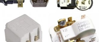
Heart! The main thing here. The refrigerator motor is usually asynchronous, so operation often requires a start-up relay. The responsibilities of the device include connecting the starting winding, only during the start. The internal bimetallic plate heats up, the capacitor is disconnected from the starting winding, and the only working one functions. Protection against overheating works according to a similar system: the refrigerator motor runs too long, the thermal effect of the current unbends the next bimetallic plate, breaking the contact, allowing the windings to rest. This scheme will allow the refrigerator to operate efficiently and provide good starting torque. It is clear that there is freon inside the device, which does not circulate happily along the circuit; the piston requires some effort. Remember here:
Refrigerator engines have individual starting requirements. The power also differs, hence the type, heating of the relay bimetallic plate does not remain constant. Special reference books have been written where we will see what types of refrigerator engines there are and what types of relays correspond. By the way, a list was posted on the site, we hope it pleased the readers. Modern refrigerator engines are inverter controlled and no longer contain a crankshaft. The shaft movement is linear, the wits have stuck the named epithet to compressors.
Inside there is a coil equipped with a core that moves forward according to the law of alternating current supplied to the wire. Despite the seeming absurdity (similarity to electric razors), the motors, as practice shows, maximally satisfy the purposes. In addition, inverter control is implemented most effectively, helping to reduce noise levels and prolong life. No wonder Samsung gives a 10-year warranty on refrigerator motors. Let us remind you:
- Asynchronous motors with a squirrel-cage rotor are capable of changing the rotation speed, including those controlled by changing the frequency of the supply voltage.
- Commutator motors, which are rarely used in refrigerators, lack this ability.
- A new type of motor made of a coil and an oscillating core is also easily controlled by changing the pulse repetition rate.
As a result, the following diagram appears:
- The input voltage is rectified.
- It is cut with a power key into the required durations.
- The work is driven by a clock pulse generator.
The simplest circuit, more likely related to a switching power supply, the essence remains the same: there is a voltage of 50 Hz, then it becomes a voltage of a different frequency. As a result, we see a change in the speed of movement of the piston, causing the freon to move faster and slower. What does this give?
Refrigerator diagram: drawing of the device and working unit
Not a single cooling-producing structure could operate without a properly designed circuit in which all elements and the sequence of their interaction are defined.
In fact, the cooling process does not occur at all as we are accustomed to believe. Refrigerators do not produce cold, but absorb heat, and because of this, the space inside the device is devoid of high temperatures. The refrigerator circuit includes all the elements of the device that are involved in providing cooling of the air inside the device, and the sequence of actions of this mechanism.
Basically, the reliability of the refrigerator depends on the quality of the compressor
From the image in the diagram you can understand the following:
- Freon enters the evaporation chamber, and passing through it takes heat from the refrigeration space;
- The refrigerant moves to the compressor, which, in turn, moves it to the condenser;
- Passing through the above system, the freon in the refrigerator cools down and turns into a liquid substance;
- The cooled refrigerant enters the evaporator, and while passing into a larger diameter tube, it turns into a gaseous mixture;
- After this, it absorbs heat from the refrigeration chamber again.
This operating principle is inherent in all compression-type refrigeration units.
Absorption refrigerators, how they work, how they work
Just as in compressor-type refrigerators, the cooling of the internal chambers in devices of this type is not associated with the production of cold, but with the evaporation of the working fluid, which is most often used as ammonia, however, in addition to it, it also contains hydrogen or some other still an inert gas.
Such devices are equipped with an absorber, desorber and reflux condenser. When ammonia is dissolved in water, the entire mixture begins to move. The solution in the absorber, due to its physical properties, moves into the desorber, where it again decomposes into two preliminary components. In the condenser, the working mixture returns to a liquid state, and then again goes to the evaporator. The movement of ammonia is ensured by jet pumps.
Most often, an absorption-type refrigerator is used where a conventional compressor unit cannot be used. In everyday life, such devices are rarely installed due to the toxic substance they contain, which is extremely toxic to humans.
Smart refrigerators with electronic control
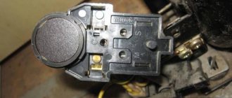
Classic thermostats, with a mechanical rotary knob and a bellows inside, are becoming less and less common in modern refrigerators. They give way to electronic boards capable of managing an ever-increasing variety of operating modes and additional refrigerator options.
The function of determining temperature instead of a bellows is performed by sensors - thermistors. They are much more accurate and compact, often installed not only in each refrigerator compartment, but also on the evaporator housing, in the ice maker and outside the refrigerator.
Many modern refrigerators have an electric air damper drive, which makes the No Frost system as efficient, convenient and accurate as possible in setting
The control electronics of many refrigerators are made on two boards. One can be called user: it is used to enter settings and display the current state. The second is system, through a microprocessor it controls all devices of the refrigerator to implement a given program.
A separate electronic module allows the use of an inverter motor in refrigerators.
Such motors do not alternate cycles of operation at maximum power and idle time, like conventional ones, but only change the number of revolutions per minute, depending on the required power. As a result, the temperature in the refrigerator chambers is constant, electricity consumption is reduced, and the operating life of the compressor is increased.
The use of electronic control boards incredibly expands the functionality of refrigerators.
Modern models can be equipped with:
- control panel with or without display, with the ability to select and set the operating mode;
- multiple NTC temperature sensors;
- FAN fans;
- additional electric motors M - for example, for crushing ice in an ice generator;
- HEATER heaters for defrosting systems, home bar, etc.;
- VALVE solenoid valves - for example, in a cooler;
- S/W switches for controlling the closing of the door and turning on additional devices;
- Wi-Fi adapter and remote control capability.
The electrical circuits of such devices are also repairable: even in the most complex system, the cause of a malfunction is often a faulty temperature sensor or similar small detail.
Side-by-side refrigerators with touch screen controls, ice maker, built-in cooler and many customization options are controlled by a fairly extensive and complex electronic board
If the refrigerator “glitches” and refuses to correctly execute the specified program, or does not turn on at all, most likely the problem concerns the circuit board or the compressor; it is better to entrust the repair to a specialist.
Freon in the refrigerator - features of the cooling system
The operating principle of the refrigeration unit is based on gas - freon, which has the ability to change state, due to which the products are cooled.
Modern cooling systems use environmentally friendly refrigerants; even if they evaporate, they will not cause harm to the body.
Let's look at how freon works in a refrigerator - the main points
- Freon is driven by a compressor.
- High pressure builds up on the rear of the dashboard.
- Low pressure develops at the evaporator.
- On the panel at the back, the refrigerant circulates in liquefied form, and on the evaporator it evaporates.
- A cold temperature regime is formed.
How freon works in a refrigerator - nuances important for the master
The unit has a special capillary tube that complements the freon tubes. The design ensures unhindered circulation of gas in the system: depending on which section it passes through, the gas passes from liquid to gaseous and vice versa.
Electrical circuit of the refrigerator and the principle of its operation
After connecting the device to the power supply, the current flows through the contact group of the thermostat, the protective relay, the inductive coil of the starting relay and the main winding of the electric motor.
While the rotor is stationary, the current is significantly higher than usual. After the starting relay is activated, the starting inductance winding is connected to the circuit. The armature turns, the current decreases, the relay opens, and the electric motor operates as usual.
After the chamber has cooled to the required temperature in the refrigeration chamber, the thermal relay is activated and breaks the power supply circuit of the electric motor. The temperature in the compartment begins to rise, and when it exceeds the set value, the engine is reconnected. The main work cycle is repeated.
A protective relay responds to the current flowing in its circuit. If the motor is overloaded, the current in its circuit increases. When it reaches the limit values, the protective relay breaks the circuit. After the engine and relay have cooled, it closes the circuit again, starting the engine. The system protects the engine from premature wear and the room from fire. The sensor in the relay is a bimetallic plate welded from strips of metals with different coefficients of thermal expansion. When heated, the plate changes its shape, bends and breaks the chain. After the plate cools, it takes on its initial head start, closing the contacts of the circuit.
Below is a diagram of a Stinol brand compression refrigerator.
Electrical circuit of a compression refrigerator
Schematic diagram of the refrigerator
Modern equipment is supplied with a large number of elements that are used to create an electrical circuit. The schematic diagram of the refrigerator is presented:
- Thermostat. This element can be electrical or mechanical; its purpose is to set the required temperature.
- Forced shutdown button to defrost the device. This element acts as a lock that can be used to break the network.
- Thermal protection relay, which eliminates the possibility of overheating. It works automatically.
- Electric motor-compressor. This device is an important structural element that ensures fluid circulation.
- Start relay. It is responsible for supplying energy.
The complex electrical circuit of the refrigerator is also represented by other elements, which provide additional functionality.
The information provided indicates that the refrigerator is represented by a complex system that reduces the temperature and maintains it at a given value. In this case, much attention is paid to the insulation of the housing, for which special materials are used. Some electrical circuits of refrigerators include a display and an electronic control unit, which increase ease of use.
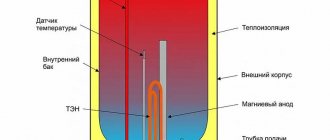
Device
The Atlant refrigerator includes the following components:
- housing equipped with double stacks with a layer of insulating material;
- front doors with the possibility of hanging on the left or right wall of the case;
- piston compressor with an electric motor (made as a single unit);
- evaporator radiator located inside the working chambers of the equipment;
- condensation unit mounted on the outer part of the case (on the rear wall);
- thermostat with temperature sensors to support specified parameters;
- electronic control unit and relays that ensure the operation of electrical components.
The radiators and compressor are connected to each other into a single unit using copper and steel tubes; solder is used to ensure tightness. The design includes additional elements that separate water or oil vapor, as well as correct the refrigerant pressure. Some refrigeration units use an additional liquid crystal display and control indicator unit. There are refrigerators with a special compartment for cooling water and with heat exchangers of the No Frost standard.
Compressor
The refrigerator compressor device includes an AC electric motor with a vertically mounted rotor. A crank mechanism is mounted on the front toe of the engine, connected to a piston that compresses the refrigerant. All units are installed on spring supports in a metal casing consisting of 2 halves. Parts of the casing are welded together by arc welding; during operation, maintenance and replacement of components are not provided.
An oil bath is located in the lower part of the housing and the power cables are entered. The motor is equipped with a double winding, the working part is used when operating the motor. An additional starting winding is applied at the moment the rotor spins up, and then is disconnected from the power circuit by a special relay installed on the outer part of the housing. A refrigerator with one compressor simultaneously serves the freezer and refrigerator compartment. The two-compressor Atlant is distinguished by the installation of separate heat exchangers and temperature controllers for 2 chambers.
Electrical diagram
The electrical circuit diagram is based on a 2-wire concept; the equipment is connected to a single-phase household network using a plug. The electrical circuit includes an additional grounding loop (only on some modifications of refrigeration equipment). To control the operation of the compressor, a relay with a built-in air temperature sensor is used. The device automatically supplies power when the chamber warms up to the set temperature; after cooling the air, a signal is transmitted to stop the electric motor rotor.
Refrigerator interior
Everyone knows how a refrigerator works, in simple words - this equipment freezes and cools a wide variety of products, allowing them to avoid spoilage for some time.
At the same time, not everyone knows certain features of this device: what the refrigerator consists of, where the cold in the inner plane of the chamber comes from, how it is created by the refrigerator and why the device turns off from time to time.
To understand these issues, it is necessary to consider in detail the principle of operation of the refrigerator. To begin with, we note that cold air masses do not arise on their own: the air temperature decreases inside the chamber during the operation of the unit.
This refrigeration equipment includes several main parts:
- refrigerant;
- evaporator;
- capacitor;
- compressor.
The compressor is the heart of any refrigeration unit. This element is responsible for circulating the refrigerant through a large number of special tubes, some of which are located at the back of the refrigerator. The remaining parts are hidden in the inside of the chamber under the panel.
During operation, the compressor, like any motor, is subject to significant heating, so it needs some time to cool down. To prevent this unit from losing its functionality due to overheating, it has a built-in relay that opens the electrical circuit at certain temperature levels.
The tubes located on the outer surface of the refrigeration equipment are the condenser. It is designed to release thermal energy outward. The compressor, pumping the refrigerant, sends it inside the condenser through high pressure. As a result, a substance with a gaseous structure (isobutane or freon) becomes liquid and begins to heat up. Excess heat is dissipated into the room so that the refrigerant cools naturally. It is for this reason that it is prohibited to install heating devices next to refrigerators.
Owners who know about the principle of operation of a refrigeration cabinet try to provide their “kitchen helper” with the most optimal conditions for cooling the condenser and compressor. This allows you to extend its service life.
To obtain cold, there is another part of the tube system in the inner chamber, into which the liquefied gaseous substance is sent after the condenser - it is called the evaporator. This element is separated from the condenser by a drying filter and a capillary. Cooling principle inside the chamber:
- Once in the evaporator, freon begins to boil and expand, again transforming into gas. In this case, thermal energy is absorbed.
- The tubes located in the chamber not only cool the air masses of the unit, but also cool themselves.
- The refrigerant is then sent back to the compressor and the cycle repeats.
To prevent nutritious foods from freezing inside the refrigerator, the equipment has a built-in thermostat. A special scale makes it possible to set the required degree of cooling, and after reaching the required values, the equipment automatically turns off.
Schematic diagram of the refrigerator
Just 30 - 40 years ago, household refrigerators had a fairly simple structure: the motor-compressor was started and turned off by 2 - 4 devices, and there was no question of using electronic control boards.
Modern models have many additional options, but the principle of operation remains generally unchanged.
In old refrigerators, all additional equipment comes down to a power indicator and a light bulb in the refrigerator compartment, which is turned off with a button when the door is closed.
The thermostat is the main and only control element with which the user can configure the operation of an old refrigerator; it is usually located inside the refrigerator compartment. The bellows spring is hidden under the power lever - the rotating handle. It contracts when the chamber is cold, thereby opening the electrical circuit and turning off the compressor.
As soon as the temperature rises, the spring straightens and closes the circuit again. The refrigerator's freezing power indicator knob regulates the permissible temperature range: the maximum at which the compressor starts and the minimum at which cooling stops.
The thermal relay performs a protective function: it controls the temperature of the engine, therefore it is located directly next to it, often combined with the starting relay. If the permissible values are exceeded, and this can be 80 degrees or more, the bimetallic plate in the relay bends and breaks the contact.
The motor will not receive power until it cools down. This protects against both compressor failure due to overheating and a house fire.
The motor-compressor has 2 windings: working and starting. Voltage is supplied to the operating winding directly after all previous relays, but this is not enough to start. When the voltage on the operating winding increases, the starting relay is activated. It gives an impulse to the starting winding, and the rotor begins to rotate. As a result, the piston compresses and pushes freon through the system.
The motor-compressor compresses and pumps freon through the system pipes, which transfers heat from the refrigerator chambers to the outside and cools the products
In general, the operating cycle of the refrigerator can be described as follows:
- Connection to the network. The temperature in the chamber is high, the thermostat contacts are closed, the motor starts.
- Freon in the compressor is compressed, its temperature rises.
- The refrigerant is forced into the condenser coil, located behind or in the refrigerator tray. There it cools, gives off heat to the air and turns into a liquid state.
- Through the dryer, freon enters a thin capillary tube.
- Entering the evaporator located inside the refrigerator chamber, the refrigerant expands sharply due to an increase in the diameter of the tubes and the transition to a gaseous state. The resulting gas has a temperature below -15 degrees and absorbs heat from the refrigerator chambers.
- The slightly heated freon enters the compressor, and everything starts all over again.
- After some time, the temperature inside the refrigerator reaches the set values, the thermostat contacts open, the motor and freon movement stop.
- Under the influence of the temperature in the room, from new warm products in the chamber and opening the door, the temperature in the chamber rises, the thermostat closes the contacts and a new cooling cycle begins.
This diagram exactly describes the operation of old single-compartment refrigerators, which have one evaporator.
Single-chamber refrigerators have a small freezer compartment, not separated by thermal insulation from the main one, and one door. Food in the front of the freezer may be thawing
Typically, the evaporator is the freezer housing at the top of the unit, not isolated from the refrigeration chamber. We will consider the differences in the design of other models below.
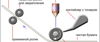
3.1. Operating principle of a compression refrigerator
The theoretical basis on which the operating principle of refrigerators is built, the diagram of which is shown in Fig. 23 is the second law of thermodynamics. The cooling gas in refrigerators undergoes the so-called reverse Carnot cycle . Moreover, the main heat transfer is based not on the Carnot cycle, but on phase transitions - evaporation and condensation. In principle, it is possible to create a refrigerator using only the Carnot cycle, but in order to achieve high performance, either a compressor creating a very high pressure or a very large area of cooling and heating heat exchanger will be required.
The refrigerant enters the evaporator under pressure through a throttling hole (capillary or expansion valve), where due to a sharp decrease in pressure, evaporates and turns into steam. In this case, the refrigerant takes away heat from the internal walls of the evaporator, due to which the internal space of the refrigerator is cooled. The compressor draws refrigerant from the evaporator in the form of steam, compresses it, due to which the temperature of the refrigerant rises and pushes it into the condenser. In the condenser, the refrigerant heated as a result of compression cools, releasing heat to the external environment, and condenses , i.e. turns into liquid. The process is repeated again. Thus, in the condenser, the refrigerant (usually freon) under the influence of high pressure condenses and turns into a liquid state, releasing heat, and in the evaporator, under the influence of low pressure, the refrigerant boils and turns into a gaseous state, absorbing heat.
A thermostatic expansion valve (TEV) is necessary to create the required pressure difference between the condenser and the evaporator at which the heat transfer cycle occurs. It allows you to correctly (most completely) fill the internal volume of the evaporator with boiled refrigerant. The flow area of the expansion valve changes as the thermal load on the evaporator decreases, and as the temperature in the chamber decreases, the amount of circulating refrigerant decreases. A capillary is an analogue of a expansion valve. It does not change its cross-section, but throttles a certain amount of refrigerant, depending on the pressure at the inlet and outlet of the capillary, its diameter and the type of refrigerant.
When the required temperature is reached, the temperature sensor opens the electrical circuit and the compressor stops. When the temperature rises (due to external factors), the sensor turns on the compressor again.
Inverter and conventional refrigerators
There are two types of compressors - conventional and inverter. They differ in their internal structure and operating mode. Previously, all refrigerators were equipped with linear ones, but now inverter ones are gaining popularity.
A conventional compressor operates in a start-stop mode. For example, when the temperature in the chamber rises 1 degree above the desired temperature, the compressor turns on and the refrigerator begins to cool. Once the temperature has reached the desired temperature, it turns off.
The inverter compressor runs constantly, but with little power. It maintains the temperature at a given level. At the same time, its total energy consumption is lower than that of a conventional one.
The advantage of a linear compressor is that it does not experience stress when turning on and off. Accordingly, its service life is much longer. But inverter equipment also costs more than conventional equipment.
In this article, we described the principle of operation of the refrigerator and touched on other topics. We hope you found it useful. Don't forget to share the post with your friends!
How to connect the start relay
Self-installation of a new mechanism must be combined with a certain level of knowledge, otherwise you should call a specialist. If the refrigerator arrived without a start relay and there was no visual inspection of its correct location, it is recommended that you read the manufacturer’s instructions.
The starting relay connection diagram is standard:
- disconnect the electrical appliance from the network;
- wait a few minutes for the equipment to completely de-energize;
- unfasten the water supply hose from the back wall and move it away so as not to accidentally damage it;
- Unscrew the fasteners securing the protective panel and put them aside;
- remove the old start relay; if it is not there, find the location on the compressor;
- connect the connector to the new device;
- insert into place;
- connect the wires according to the markings;
- secure the trigger mechanism with screws and latches;
- put the back panel in place, screw it on;
- attach the water supply hose, secure;
- plug into the electrical network for testing.
Professionals recommend using protective gloves to prevent hand injuries. Independently connecting modern types of starting relays can cause a number of difficulties that are not always possible to correct on your own.
The start relay is an important part of the refrigerator that starts the electric motor and protects the equipment from breakdowns. Failure of an element leads to the appearance of uncharacteristic noise and equipment not turning on. You can identify the malfunction, carry out repairs, and replace it yourself, but in the absence of certain knowledge, it is better to turn to specialists.
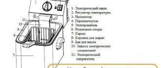
Oil refrigerator diagram
The oil cooler works in conjunction with a fan in the diffuser socket. Hot oil enters the lower manifold and passes up and down through the refrigerator tubes, cooled by the air flow created by the fan.
During normal operation, the temperature of the oil leaving the refrigerator should be 18-20 degrees lower than the temperature of the incoming hot oil. The cooled liquid is discharged through an opening in the upper manifold.
The fan creates a flow of air that passes through the core of the oil cooler and removes heat from its tubes. The station's fans are designed similarly to rotary, screw and piston compressors. The air collector, which is a container for compressed air and oil, also performs the function of separating them from each other.
Inside the air collector, consisting of a steel shell and two bottoms, there is an oil separator - a pipe with filter bags, closed with a steel lid. Oil is poured through the neck, its level is determined with a dipstick. To release condensate accumulated in the sump or drain oil from the oil sump, a drain pipe with a tap is provided.
The oil-air mixture enters the air collector at high speed, where, due to its large volume, its speed sharply decreases and the oil droplets cool in its lower part. After preliminary cleaning, the compressed air passes through the filter bags of the oil separator, where it is finally cleared of oil. The oil accumulated in the lower part of the oil separator is sucked out by the pump and returned to the oil sump for reuse.
If the outer surface of the tubes and cooling plates is contaminated, blow the core of the oil cooler with compressed air in the direction opposite to the air flow created by the fan. When the outer surface of the refrigerator becomes oily, wash the tubes and plates with white spirit or other special liquids.
If the inner surface of the tubes is contaminated with oil oxidation products, remove the core of the oil cooler and immerse it in kerosene for 24 hours, after which the tubes are cleaned by repeatedly pushing a rag swab inside the tubes.
The oil cooler is made of aluminum alloy and has external cooling fins. The oil cooler and oil filter are installed on the flywheel side of the engine. The refrigerator consists of sections, each of which is a set of brass radiator tubes soldered to the base. To increase the cooling surface, the pipes have ribs. The sections are installed between slabs, which are connected by posts. Side covers are attached to the plates, and the left one is divided inside by an edge into two halves, each of which has a flange for connecting the pipeline.
The radiator-type oil cooler is located in front of the main water-cooling radiator. Oil filters come in pre-cleaning types of Cunot (plate, cleanable) and fine filters (double with cartridges made of cotton ends).
Working principle of absorption refrigerator
Absorption is the process of absorption of a substance by another substance. So, moisture can absorb ammonia, which is why ammonia is formed, while salt, for example, absorbs moisture. Absorption refrigerators work on the same principle. If initially refrigeration units of this type appeared due to the study of the possibility of using liquid fuel, with the development of industry, compression units practically forced them out of the market. However, then more and more new technologies appeared, and today both operating principles are used equally in the production of refrigeration machines.
Instead of a compressor, absorption refrigerators use a type of “boiler” that is heated by an electrical current. The boiler contains ammonia, which turns into steam due to heating, and accordingly increases the pressure in the device. Under the influence of simple laws of physics, ammonia vapor moves to the condenser, where it cools and turns into a liquid state again. The operating scheme itself is almost identical to that of a compression refrigerator. An absorption refrigerator is much quieter than its compression “brother”, does not depend on power surges in the network and does not have moving parts that easily fail. But it also has its drawbacks: electrical energy consumption increases slightly, which leads to financial costs.
Morozko refrigerators operate on this operating principle.
Refrigeration process
In evaporator 10, boiling freon takes heat from the cooled water in tank 12 (Fig. 3). Cold freon vapor passes into compressor 1 through heat exchanger 4, where it is heated to a temperature of 273 K (0 °C) by liquid freon entering through filter drier 5 from receiver 3. The pressure in the suction side of compressor 1 is 150...200 kPa. Compressor 1 compresses freon vapor to a pressure of 0.9…1.1 MPa. The temperature of the latter rises to 330..350 K (up to 80 °C).
Then the hot freon enters condenser 2, where it is cooled by air blown by fan 13 through the tubes of condenser 2, while gaseous freon turns into a liquid state, i.e., condenses. In the condenser, 2 pairs of freon are cooled by air supplied by fan 13 to a condensation temperature of about 30 °C. Liquid freon flows from condenser 2 into receiver-storage 3, from the receiver into filter-drier 5.
Rice. 3. Technological diagram of the working process of the refrigeration unit: 1 – compressor; 2 – capacitor; 3 – receiver; 4 – heat exchanger; 5 – filter drier; 6 – viewing device; 7 – thermostatic valve; 8 – water pump; 9 – plate cooler; 10 – cold accumulator (evaporator); 11 – pressure switch; 12 – tank; 13 – fan; 14 – thermal relay
Having passed the filter drier 5, the freon enters the heat exchanger 4, where the liquid freon is cooled by the freon sucked by the compressor 1 from the evaporator 10.
From heat exchanger 4, liquid freon flows through the inspection window to thermostatic valve 7. Due to the small cross-section of the passage hole of thermal valve 7, the freon entering through it into the evaporator 10 is throttled, and its pressure drops sharply (to 0.1...0.3 MPa).
In evaporator 10, liquid freon boils, turning into steam. The low pressure in the evaporator 10 determines the low boiling point of the freon entering it. Boiling freon takes away heat from the coolant (water) located in tank 12. As freon moves through the evaporator channel 10, the amount of liquid freon decreases, and the amount of vapor formed as a result of boiling increases. Dry, superheated freon vapors from the evaporator 10 are sucked off by compressor 1. Cooled water is supplied by a water pump to the plate cooler 9. The circular operating cycle is then repeated.
When the refrigeration machine operates in automatic mode, the thermal relay 14 maintains the water temperature in the cold accumulator 10 within the range of 273.5...276 K (0.5...3.0 °C).
If necessary, ice can be obtained from the cold accumulator 10 by freezing it on the evaporator panels 10.
Pressure switch 11, thermostatic valve 7, thermal relay 14 and temperature sensor make it possible to maintain freon pressure on the high and low pressure lines within specified limits, regulate the filling of the evaporator 10 with liquid freon, and also maintain a given temperature of freon vapor in the cold accumulator 10 when ice is frozen and set water temperature.
Refrigerator without electricity - fact or fiction?
Nigerian resident Mohammed Ba Abba received a patent for a refrigerator without electricity in 2003. The device consists of clay pots of different sizes. The vessels are stacked into each other according to the Russian “matryoshka” principle.
Refrigerator without electricity
The space between the pots is filled with wet sand. A damp cloth is used as a cover. Under the influence of hot air, moisture from the sand evaporates. The evaporation of water leads to a decrease in the temperature inside the vessels. This allows you to store food for a long time in hot climates without using electricity.
Knowledge of the structure and operating principle of the refrigerator will allow you to perform simple repairs of the device yourself. If the system is configured correctly, then the device will work for many years. For more complex malfunctions, you should contact service center specialists.