A big request to readers is not to consider the first paragraph a journalistic technique...
Recently, my “Home-made” amplifier began to jam a little on one channel, and I had to get serious about checking the details. It turned out that the whole issue was a low-quality capacitor at the input.
After the repair was completed, I was persuaded to temporarily borrow this amplifier with speakers for “events” (it was just the holidays). What can you do at home when there is nothing to connect to the sound card output, but you want to listen to music or just play another shooter (currently “Call of Duty”)?
So I took out of the closet the fairly dusty Cheburashka speakers that I had once used. Their price was something like 300 rubles, and they reproduced music with appropriate quality. So after “high-quality” sound (a good amplifier + more or less normal speakers), it became simply unbearable to hear the cardboard sounds made by the stunted little ones.
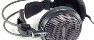
But there was still a headphone output on the Cheburashkas. Okay, so it's time to use the headphones. In stores, among all sorts of different “products”, I came across a headset from SONY CD-268M.V.
Of course, connoisseurs of quality will frown with displeasure - yes, the truth is yours, because the price of these “burdocks” is about 10 USD, and not 100... But compared to the screams of “buttons” for 30 rubles, this was “Sound”.
Although, of course, it’s still far from “SOUND” (the Cheburashkas were noticeably loud...).
Headphones could be connected directly to the output of the sound card, but one question arose - what kind of load are these outputs actually designed for?
The fact is that distortion measurements are almost always made when the output of the sound card is loaded onto the input of the measuring device, and its input resistance is unlikely to be 32 Ohms. But as the load resistance decreases, the current increases, and now as the volume increases, distortion increases - look at the characteristics of any microcircuit - a low-frequency amplifier (graphs are in almost every description).
It turns out that when connecting headphones, the sound card is unlikely to be able to provide a high standard of sound quality and fully reveal its potential. (Or will it still be able to?)
So the idea came to build an amplifier specifically for connecting headphones - after all, the homemade amplifier does not have a special jack (the circuit design is such that ordinary headphones simply cannot be connected there). There were quite a lot of schemes in magazines and on the Internet, but only four were chosen.
The quality of their “sound products” increases gradually, and the complexity of assembly practically does not increase. I hope many music lovers and gamers will find useful information here. And the wives will be able to take a break from the music and noise... (Only now it will be much more difficult for them to shout to you.)
Attention! Constant use of headphones at maximum volume leads to permanent hearing loss! Ministry of Health warns!
Scheme one, simple
The headphone amplifier circuit is quite simple. (Author - Valenty Svyaty, Practyczny Elektronik No. 2/2000, p. 4–6.) Actually, which, with a supply voltage of 9 Volts, can develop up to 1 W at a load of 8 Ohms. The microcircuit operates normally at loads up to 4 ohms and, with an output power of 150 mW, provides a harmonic coefficient of no more than 0.2%. This means that when working with headphones, the amplifier will not overwork, it will not get very hot and will not distort the sound.
The main feature of this circuit is automatic power on/off. When an audio signal is applied to the input of the amplifier, the voltage at the output of the detector on diodes VD1, VD2 becomes sufficient to open transistor VT2, which then opens transistor VT1, through which the supply voltage passes to the microcircuit.
The amplifier is powered by a 9-volt battery (Krona, for example). If there is no sound signal, the voltage at the detector output decreases to zero, the transistors close and the microcircuit is de-energized. The headphone amplifier is operational at a supply voltage of 1.8 to 15 Volts.
Naturally, if you do not suffer from forgetfulness, you can throw out the “extra” parts from the circuit (detector and transistor switch) and install a simple switch in the power circuit.
A simple class A amplifier.
Nikolay Troshin
This article is a continuation of work on the topic of using amplifiers operating in class A for high-quality sound amplification. I present for your consideration a well-developed amplifier circuit using silicon transistors. An undeniable advantage of silicon is its ability to operate at much higher temperatures (compared to germanium). If there is good thermal contact between the transistor and the radiator, a radiator temperature of 90...95 degrees can be considered acceptable.
It is clear that with such a high temperature difference between the radiator and the environment, heat exchange occurs very efficiently. Therefore, with the same areas of the output transistor radiators, silicon can produce approximately 2 times more power compared to germanium. A large assortment of high-power silicon mid- and high-frequency transistors allows you to build a high-quality Class A amplifier with a very simple circuit.
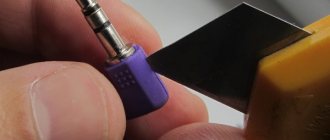
This circuit provides an output power of 20 watts into a 4 ohm load. The operating frequency range of the amplifier is 20…25000 Hz. As a transistor VT1 here you can use KT208D, KT209D, KT361G, E, KT3107B, G, I, K. As a transistor VT2, you can use transistors KT815, KT801, P701, transistor VT3 KT814, VT4 - KT818BM, GM, transistor VT5 - KT819BM - KT819BM - KT819BM - KT819BM - KT819BM - KT819BM - KT819BM - KT819BM , GM. The circuit can operate without selecting transistors based on the gain, however, since it contains only 2 amplification stages, it is desirable to have a gain of transistor VT1 of at least 150, transistors VT2, VT5 of at least 50, transistor VT4 of at least 80. Estimate the gain of the transistor not difficult. It is enough to turn on the transistor under test according to this circuit (for powerful transistors).
Resistor R1 provides approximately 1 mA of current to the base. The measuring milliammeter measures the collector current (I used a dial tester with a measurement limit of 300 mA). The ratio of the collector current to the base current will be the gain of the transistor. For medium power transistors, it is necessary to reduce the base current by 10 times (R1 36k), and for a low power transistor, we reduce the base current by 100 times (R1 360k). As a power source, I used 3 alkaline (alkaline) AA batteries, which I simply soldered together with a well-heated soldering iron, using a thin wire (you need to solder quickly so as not to overheat the battery).
When using an 8 ohm load, the supply voltage must be increased to 39...40 volts, resistor R10 to 0.25 ohms. Setting up the amplifier comes down to setting half the supply voltage on the VT5 collector. The amplifier consumes significant power, approximately 100 watts per channel. Therefore, the power source must be serious. A power transformer for the power supply must be used with a power of at least 250 watts, or use two transformers of the same type (for each channel) with the same total power. The power supply circuit is shown in the figure below.
The secondary winding of the power transformer must have an output voltage of XX 26 - 27 volts. Such a circuit should be for each channel of the amplifier, and with a load of 4 ohms, it may be better to immediately install 22,000 μF capacitors. A diode bridge with a rated current of at least 10 A or 4 diodes of 10 A. The large capacitance of the capacitors is explained by the significant current consumption, including in the amplifier's idle mode, when ripple is especially noticeable. I did not use electronic filters or stabilizers, since they sometimes cause self-excitation of the amplifier and are a source of interference and interference.
Parts for the amplifier: Resistors can be of any power of at least 0.125 watts with the exception of R9 5 watts, R10 2 watts. The value of resistor R10 is very important. The correct operating mode of the amplifier depends on this. It is better to use film capacitor C1, film or mica capacitor C4. Output transistors KT818, KT819 must have the letter “M” at the end (in a metal case), BM, GM. I used ribbed radiators for them, size 120*170, thickness 35 mm. If the radiators are smaller, then forced airflow is required. On KT815 there is a small radiator plate of 2-3 square meters. see. On P701 a radiator is not needed. Resistor R9 dissipates significant power. If you have an oscilloscope and a generator, you can try to reduce it. We apply a signal to the input, connect a load equivalent and an oscilloscope to the output. With resistor R4 we achieve a symmetrical limitation of the maximum possible signal amplitude. Next, by increasing resistor R9, we achieve the beginning of limiting the signal from above. We solder and measure the nominal value. After this, set the resistor 25...30% smaller. If you want to experiment, you can put together a completely simplified circuit.
Transistors here should have a higher K. The first is at least 200, the second is at least 100. Resistor R7 with a power of at least 50 watts. If this is not available, you can use an electric kettle and an iron of 2000 watts at 220V, connected in parallel, or 2 heating elements for 2000 watts. - the result is a resistance of about 10 ohms. By the way, this can also be used as a load equivalent. This circuit allows you to get 4...5 watts (it will still consume about 90 watts.) You need to set 12 volts on the VT2 collector. Good luck with your creativity and design!
Scheme two, advanced
A headphone amplifier circuit called “Volume and tone control unit for stereo headphones” caught my eye. (Author - Andrzej Kosminski, Hobby Elektronik, No. 2/2000, pp. 48–49). The volume and tone controls themselves are made on the A1 chip - TDA1524A in a typical switching circuit. (This was written in the magazine; in the original description of the microcircuit, the circuit is slightly different. But here the circuit is presented in its “published” form).
A “powerful” amplifier capable of driving low-impedance headphones is assembled on the dual operational amplifier A2.
Depth of volume control (R2) from –80 to +21 dB, bass tone (R4) +/- 12 dB at a frequency of 100 Hz, treble tone (R5) +/- 10 dB at a frequency of 10 kHz.
The maximum input voltage is no more than 2.5 Volts, supply voltage 12 Volts, current consumption 40 mA. The adjusting resistors should be 47 kOhm with a linear dependence of the change in resistance on the angle of rotation of the engine (the so-called group “A”).
There shouldn't be any difficulties in manufacturing. If you want to power the amplifier from a +12 Volt source from the computer's power supply, you will have to take measures to protect against interference in the power circuits (in the same way as car radio manufacturers do - they install special filters).
Fans of shooting games can limit themselves to these designs, but music lovers are encouraged to read the text further.
Why do you need a headphone amplifier?
The question of whether it is necessary to amplify the sound in headphones worries many headphone users. After all, almost every device that reproduces audio signals (player, radio, personal computer, smartphone, etc.) has a built-in amplifier equipped with a separate output for connecting headphones. Moreover, measurements of the parameters of the built-in amplifiers, carried out without connecting a load (at idle), show that they all meet the requirements necessary for high-quality sound from headphones. However, the thing is that when connected to a playback device, the situation changes dramatically, and not for the better. And the problem lies precisely in the coordination of these devices with each other.
Advice! Therefore, experts advise that when connecting headphones to a sound source, pay special attention to the load resistance recommended by the manufacturer of the latter. Otherwise, when listening to soundtracks, distortions will occur that can significantly degrade the sound quality.
If the output impedance of the sound reproducing device does not match the impedance of the headphones, the following consequences are possible:
- the high sensitivity of low-impedance headphones contributes to the appearance of background noise;
- when connecting high-impedance headphones to a low-impedance input of a sound source, the sound volume of the phonogram may be significantly reduced, etc.
You can avoid these problems if you connect your headphones to the sound source through an external amplification device with a sufficiently large (over 20 kOhm) input impedance . Such a device interacts perfectly with any built-in amplifier, since the operation of the latter with a high-impedance load is not much different from its operation at idle. You can learn more about headphone impedance in our article.
On a note! The built-in amplifier easily provides the maximum possible performance of the playback device, but it is the task of the headphone amplifier to fully unleash the potential of the connected headphones.
The third version of a headphone amplifier, cool
This circuit is a slightly reworked version of an amplifier from the “almost Hi-End” category (don’t let fans of tubes wince - there are also transistor circuits of this class). The scheme was published in the magazine “Radiohobby”, No. 6, 2003, author - Vyacheslav Shchutsky.
In its original form, it was a class “A” amplifier with an output power of 25 Watts into a 4 Ohm load, a power dissipation of 60 Watts and a quiescent current of the output transistors of 2 Amps (!).
This is a complete unit that is an input voltage repeater with a voltage gain slightly less than unity. It had to work with a high quality voltage amplifier. (The sound card will fully provide this amplifier with the required signal level; it only needs to be amplified in power.)
The load (in the original) should be highly sensitive acoustic systems, for example, monitor type. In this case, this “heater” will be used as a headphone amplifier.
Naturally, the quiescent current can be made smaller (for this you will have to change the resistance value of some resistors), and replace the output transistors with KT854A (we had to leave the KT819 transistors in the circuit - there were no others available). The capacitors, oh, were installed during revision. The values in parentheses refer to the “original” amplifier circuit (if you need to get 25 Watts at the output).
In this circuit it is clear that the amplifier does not have feedback, which, according to many experts, makes it difficult to feel the difference between the circuits. But at the same time, the requirements for the quality of each element of the circuit increase, which will be discussed later. Let's look specifically at the features of this development.
The input stage of the amplifier is made according to a circuit with a common collector (CC) on transistor VT1 with an active load in the emitter circuit in the form of a stable current source (IST) on transistors VT2, VT3. Transistors VT2, VT3 are installed on a common heat sink with an area of 30...40 cm2.
This circuit design makes it possible to install transistors on a common heat sink and ensures high stability of the IST current and the quiescent current of the output transistors. The collector current of the input transistor flows into the base of the transistor VT5, on which the IST for the output amplifier transistor VT4 (Push-Pull principle) is built.
The output amplifier transistor VT4 is also connected according to a “common collector” circuit, and the entire amplifier is assembled according to the “OK-OK” circuit. Transistors VT4, VT5 in the original version were installed on a common heat sink with an area of about 800 cm2.
To drive the headphones, you need very little power, so we’ll set the quiescent current lower, the power dissipation will be reduced and, therefore, there will be no need for a “monstrous” radiator. In the manufacture of the “ear” amplifier, a relatively small radiator from P-II was used, on which all five transistors were installed through insulating gaskets made of thermal film or mica (first strengthen the transistors, check with an ohmmeter for absence of short circuits to the radiator, and only then solder!).
Naturally, you will need two such radiators - one for each channel. The fans can be removed, but if it turns out that the heating of the radiators is too high (more than 80°C), you will have to return them to their place (maybe you can reduce the quiescent current?).
Setting up the amplifier is done as follows. Before turning on, the correct installation is checked, the trimmer resistor slider is set to the middle position. After switching on, it is necessary to check the potential at the emitter of VT4 (half the supply voltage).
If the voltage is different from 6 Volts, adjust the trimming resistor. After setting it up, you can replace it with fixed resistors, you can guess how exactly. In the manufactured sample, the quiescent current of the first channel is 120 mA, the quiescent current of the second channel is 240 mA. Despite such a noticeable difference (the transistors are to blame - I had to install KT814 with different letter indices, hence the scatter), it was not possible to detect any differences in sound quality (probably because the headphones are not too expensive or the ears are deaf). But it is still better to select transistors in the channels so that the quiescent currents are approximately equal.
If the quiescent current is insufficient, the resistance value of resistor R5 should be reduced. If necessary, you can additionally adjust the voltage at the VT4 emitter by visually monitoring the uniformity of the limitation of the sinusoid with a frequency of 400...1000 Hz (top and bottom) on the oscilloscope screen with a connected load. During setup, a resistor with a resistance of, for example, 33 Ohms can act as a load (we choose it approximately equal to the resistance of the headphone winding).
Now - about the details of the rectifier. Its diagram is not given because it is a standard bridge. It is better to use rectifier diodes with a large crystal area, for example KD213. The capacity of the electrolytic capacitors in the rectifier is based on the principle “the more, the better” (in the manufactured sample, two 4700 μF capacitors with a maximum voltage of 25 Volts are installed “in parallel”). The voltage at the rectifier output must be at least 15 Volts.
But it will not be possible to power the amplifier from a simple bridge rectifier. The fact is that amplifiers of this type are very sensitive to supply voltage ripples. You will need to make a small 12 Volt voltage stabilizer. For this purpose, a suitable microcircuit is a voltage stabilizer 7806, connected according to the circuit shown in the figure.
The zener diode helps increase the output voltage of the stabilizer to the required 12 Volts (or rather, there will be 6 + 5.6 = 11.6 Volts, but these are minor things). The current consumption is small, so the radiator for the stabilizer chip can be used small in size.
To reduce the influence of stereo amplifier channels on each other, companies use tricks of varying degrees of “steepness” - for example, completely separate block designs (two “monoblocks”), power from different transformers, power from separate windings of one transformer, power from different rectifiers connected to one winding of the transformer. Choose for yourself which option suits you best. Another recommendation is to place capacitors of another type, for example MBGO or MBGCH, in parallel with the electrolytic capacitors in the power supply circuit - this improves the sound of the amplifier at higher frequencies of the audio range. You can select the capacitance value of such capacitors yourself, based on your hearing.
The recommended type of capacitor C1 is the so-called “paper-oil” (at least MBM), the output electrolytic capacitor is type K50-29V or imported (Elina for Audio, Marcon). But you can also install more affordable ones, if you check and select the best ones according to the parameters. It is also possible to connect smaller capacitors in parallel. For example, instead of a 2200 uF output capacitor, two 1000 uF capacitors had to be connected in parallel (). MLT type resistors with power dissipation 0.25…0.5 W.
It is believed that the larger the element, the less noise it creates. I suggest you check it out for yourself.
The printed circuit board for this amplifier was not developed; all installation was performed with a single-core insulated wire. If you wish, you can perform the entire installation with silver-plated copper wire (then you will proudly show off your amplifier to your friends - just make the case in a modder style, with a transparent window and LED backlighting).
The case for this experimental sample of a headphone amplifier was made of foil fiberglass, with radiators for channel amplifiers mounted on the side covers. True, the design turned out to be something vaguely reminiscent of the English tank “Big Willie” from the First World War. The LED power indicator, headphone jacks and parallel amplifier jack are located on the front panel.
The frequency response of the amplifier is linear, the range of reproduced frequencies is from 20 Hz to 120 kHz (the generator’s capabilities were not sufficient beyond that). There was no need to adjust the timbre while listening to music.
The magnitude of nonlinear distortions could not be measured due to the lack of necessary instruments. But we can hope that the distortion will be very small - after all, the transistors operate in class “A” mode. It is impossible to detect any noise when the amplifier is turned on - there is complete silence in the headphones during pauses. What you need to get...
And I also liked playing - during the explosions of grenades and shells, there were no creaks or overtones in the headphones - only what the developers wanted to “voice”.
A headphone amplifier can be used for comparative testing of stereo headphones, and playing is also not forbidden. But it is recommended to listen to high-quality music, otherwise all the shortcomings (sound card noise, wheezing of headphones, interference from drives, etc.) will show themselves very clearly.
Of course, it was possible to conduct comparative studies on the topic “The difference in the sound quality of stereo phones when they are connected directly to the output of a sound card and a specialized amplifier” with the involvement of a crowd of experts and piles of measuring instruments, but then the entire volume of the article would have to be devoted only to this topic.
Maybe it seemed to you that there was no need to sculpt such a bulky box for playback only through headphones? Then why do people pay such ridiculous amounts of money (go to www.hi-fi.ru and look at the prices) for amplifiers, speakers, and even connecting cables?
Yes, of course, this device will be inferior in characteristics to amplifiers assembled on tubes and transformers wound with silver wire (Audio Note, etc.) But still, compared to the work of Chinese assemblers, the sound of this homemade product is completely different - I checked it personally.
CLASS A AMPLIFIER FOR HEADPHONES
Dissatisfaction with the quality of playback of musical compositions by the computer sound card forced me to start making a desktop amplifier. I decided that it would be a simple homemade headphone amplifier, assembled according to a classical circuit on a single transistor stage.
However, there is a note. This amplifier will be suitable only when the input signal does not require voltage amplification (for example, an MP3 player or computer provides a sufficient output). Also, any noise generated in the power supply will go straight through the amplifier. For this reason, it is necessary to use only a stabilized power supply. Output voltage range 10-20V and current 750mA. It uses an N-channel MOS transistor with a reverse diode for operation in switching and linear modes IRF610. During the manufacturing process of the amplifier, the use of other transistors was tested: IRF510, IRF611, IRF612 and IRF710, all without exception worked well. I recommend not using IRF530 and IRF540 (commonly found in power supplies). The LM317 used is a stabilizer with adjustable output voltage that allows you to very accurately adjust the output parameters of the power supply.
Since this amplifier will be sitting on a desk in a production office, it needs to fit in with the work environment. I was lucky that there was a failed external CD-ROM, its design was perfect. In addition, its case already had a switch, power adapter, RCA socket and inputs on the rear panel, as well as a headphone jack on the front panel.
In the manufacture of the amplifier, only those electronic components and components that were available were used. Conventional resistors and film capacitors. Capacitors with a capacity of 1 µF, 0.47 µF and 0.1 µF are polypropylene. But no one is stopping you from using higher quality parts.
Cooling radiators have a relatively small volume of cooling area, but I draw your attention to the fact that they are screwed directly to the metal body, which also takes part in heat dissipation. The smaller radiator has a volume of approximately 1.75 square inches. Be sure to isolate the MOSFET and regulator from the heatsinks.
The operation of the amplifier was tested using an regulated power supply; it was turned on at low voltage. The bias is set using a 100 kOhm variable resistor. The amplifier showed good performance over the entire voltage range from 10 to 20 V, but still high-quality sound reproduction began at a supply voltage of more than 13 volts.
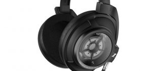
Next, the operation of the amplifier was checked using a USB oscilloscope. This is a DSO-2150 with 60 MHz bandwidth and a maximum sampling rate of 150 µ/s. The sine wave we saw showed itself at its best from 20 Hz to 20 kHz.
Square wave 100 Hz
Square 4800 Hz
Green is the input signal, and yellow is the output. The signal power of my generator is not high and this is reflected in the quality of the original waves. If you compare the input voltage and output voltage you will see that the circuit gain is about 0.8. It can be seen that at 100 Hz there is a slight slope. The slope gradually decreases and the frequency increases and beyond about 300 Hz the squared wave response is excellent up to 20 kHz - the limit of the oscillator signal. Since the music consists mainly of sine waves this is not a problem. Since an MP-3 player or computer will be used to adjust the volume, there is no need for a potentiometer. Another ULF, but using lamps, can be viewed here.
Fourth headphone amplifier circuit, for those “moved” to the tube side
This headphone amplifier circuit (author - B. Kainka, Elektor Electronics magazine, No. 10/2003, p. 70) uses a lamp that was used in radio stations that were once in service with the Soviet Army (R-105M, R- 108M, R-109M and others). And in DOSAAF, such radio stations were used for a very long time - for example, the R-108M was suitable for operating in the 28 MHz range.
Lamp 1P24B - direct filament pentode, rod type, small-sized. The filament voltage indicated in the diagram is 1.2 Volts at a current of 240 mA.
The anode voltage here is low - only 12 Volts, so you don’t have to worry about hundreds of volts coming from the anode circuit.
Headphones are connected directly to the anode circuit, the winding resistance of which must be at least 600 Ohms (they say that there are such “ears” from the “studio” category). And of course, you will need two such lamps - after all, we are supposed to have “stereo”...
The power supply circuit is not given specifically - if you are going to solder this circuit and have found such lamps that are not very common on the market, then in the future you will definitely not need my help in this particular area.