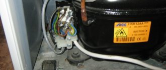
Any modern electromechanical equipment is equipped with special devices that regulate its operation and protect it from overloads. In refrigerators of any manufacturer, such a device is a start-up relay. Thermal relays play an important role in refrigeration units. Its malfunction can lead to incorrect cooling mode and loss of equipment functionality.
Start-up relay - top view
Start relay connection diagram
This device is necessary to start a single-phase asynchronous compressor motor. The motor stator includes two windings - starting and working. The first serves only to create starting torque and start the compressor. The second winding is needed to maintain the rotor in working condition by continuously supplying alternating current to it.
Important! To regulate the process of supplying and turning off power to the starting and operating windings of the electric motor, as well as for the overload protection function, a starting protection relay is provided.
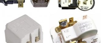
Inductive closing mechanism
The relay connection diagram is not complicated. Conditionally “zero” and “phase” power is supplied to the input of the device, and at the output “phase” is divided into two lines. The first line is connected to the working winding of the electric motor, and the second line is connected to the starting winding through the starting contact.
In relays of old and modern refrigerators, current is supplied to the working winding through a spring with high resistance, and then through a connection with a bimetallic jumper. With a strong increase in current in the circuit (motor jamming, short circuit between turns, and other breakdowns), the spring in contact with the jumper heats up, which changes its shape under the influence of temperature, thereby opening the contact and turning off the compressor.
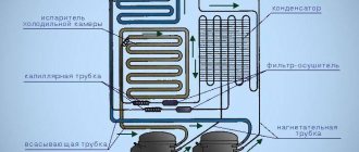
Inductive circuit circuit
In this circuit, a coil (K1) is used to start the electric motor, which is connected in series with the working winding. Applying voltage while the motor rotor is stationary provokes an increase in current in the coil with the formation of a magnetic field that attracts a movable core that closes the starting contact. After the rotor picks up speed, the current in the circuit decreases, the magnetic field in the solenoid decreases, and the starting contact opens by gravity or a compensating spring.
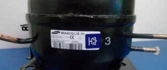
PTC switching mechanism
Modern household refrigerators use a start-up relay with a built-in posistor (a resistor that increases resistance as the temperature rises). The circuit of this device (Fig. 2) is similar to an induction relay, only instead of a coil, a posistor connected to the starting circuit is used to close and open the starting contact.
When power is supplied to the compressor, the temperature of the resistor is low and it passes current to the starting winding. Since the resistor initially has resistance, it heats up and opens the circuit of the starting winding of the engine. The cycle is repeated after the thermostat is triggered and the refrigerator is then turned on again.
PTC switching mechanism
Operating principle of the start relay
Despite the large number of manufacturers of components for refrigerators, the operating scheme and design of starting relays are almost the same. Having understood the principle of their operation, you can independently find and fix the problem.
Device diagram and connection to the compressor
The relay circuitry has two inputs from the power supply and three outputs to the compressor. One input (conditionally zero) passes directly, and the other (conditionally phase) inside the device is split into two:
- the first passes directly to the working winding;
- the second passes through the disconnecting contacts to the starting winding.
If the relay does not have a seat, then when connecting to the compressor you must not make a mistake with the order of connecting the contacts. Methods common on the Internet for determining winding types by measuring resistance are not correct in general, since some motors have the same resistance of the starting and running windings.
The electrical circuit of the start-up relay may have minor modifications depending on the manufacturer. For example, the protective block can be placed on the core, which is located below in the figure
Therefore, it is necessary to find documentation or disassemble the compressor to understand the location of the feed-through contacts. This can also be done if there are symbolic identifiers near the outputs:
- “S” – starting winding;
- “R” – working winding;
- “C” – general output.
The relays differ in the way they are mounted on the frame of the refrigerator or on the compressor. They also have their own current characteristics, so when replacing it is necessary to select a completely identical device, or better yet, the same model.
Closing contacts using an induction coil
An electromagnetic starting relay works by closing a contact to pass current through the starting winding. The main operating element of the device is a solenoid coil connected in series with the main winding of the motor.
At the moment the compressor starts, with the rotor static, a large starting current passes through the solenoid. As a result, a magnetic field is created that moves the core (armature) with a conductive strip installed on it, which closes the contact of the starting winding. The rotor begins to accelerate.
As the rotor speed increases, the amount of current passing through the coil decreases, as a result of which the magnetic field voltage decreases. Under the action of a compensating spring or gravity, the core returns to its original position and the contact opens.
On the cover of the relay with the induction coil there is an “up” arrow, which indicates the correct position of the device in space. If it is placed differently, then the contacts will not open under the influence of gravity
The compressor motor continues to operate in the mode of maintaining rotor rotation, passing current through the working winding. The next time the relay will work only after the rotor stops.
Regulation of current supply with a posistor
Relays produced for modern refrigerators often use a posistor - a type of thermal resistor. For this device, there is a temperature range below which it passes current with little resistance, and above which the resistance increases sharply and the circuit opens.
In a starting relay, a posistor is integrated into the circuit leading to the starting winding. At room temperature, the resistance of this element is insignificant, so when the compressor starts operating, current flows unhindered.
Due to the presence of resistance, the posistor gradually heats up and when a certain temperature is reached, the circuit opens. It cools down only after the current supply to the compressor is stopped and starts skipping again when the engine is turned on again.
The posistor has the shape of a low cylinder, which is why professional electricians often call it a “tablet”.
Thermal relay circuit
The thermostat in a refrigeration unit plays the role of a device that maintains operation at a given temperature by periodically turning the compressor on and off. At the present stage, 2 types of thermal relays are used:
- Mechanical devices are used in old refrigerators, as well as in such modern manufacturers as Indesit, Stinol, Atlant.
Mechanical thermostat diagram
This device is of a manometric type. The bellows and its tube (sealed corrugated metal container) are filled with freon or chlormethyl, which is in the form of steam. The pressure of the working medium changes directly proportionally with temperature changes. At the end of the tube, freon is in a liquid state and is pressed against the evaporator.
As the temperature increases, the pressure of the bellows on the spring increases, the lever is activated, and the contact closes. When the temperature decreases, the opposite happens. The contact opening mode depends on the spring force, which is adjusted by the control knob.
- Electronic thermostats are used in refrigerators from manufacturers such as Samsung, Beko, LG.
Mechanical thermostats rely on the temperature in the evaporator in their operation, while electronic thermostats rely on the air temperature in the chamber. The positive aspect of electronic models is the ability to display temperature (that is, a person can visually assess the operation of the thermostat) and less error.
Electronic thermostat circuit
The temperature controller in this circuit is the LM335 temperature sensor. The device is a zener diode, sensitive to temperature changes. The climate in the refrigerator chamber is regulated by variable resistance R4. When the air temperature rises, a signal appears at the output of the TLC271 comparator, opening the KT3102 transistor, which starts the refrigerator. Accordingly, when the temperature drops, zero appears at the output of the comparator and the compressor turns off.
Checking the refrigerator relay for functionality
If the refrigeration unit does not turn on or does not turn on regularly, then most likely the problem is with the start relay. The reason for its malfunction may be:
- Oxidation or burnt contacts.
- Mechanical damage.
- Overheating of the posistor element.
- Failure to secure the relay, leading to its incorrect positioning.
- Spiral burnout.
- Core jamming.
There is no need to rush to buy a new refrigerator relay, it is better to find out how to test it and try to do it.
In the induction mechanism, the solenoid is pulled out, the contacts are checked, and if oxidized, they are cleaned with sandpaper. The core may be broken, then it needs to be replaced. Wipe contacting surfaces with alcohol. Check the integrity of all elements. It must be remembered that relays of this type are installed strictly in a certain direction, indicated by the arrow. After the above steps, connect the relay to the compressor and turn on the refrigerator. If the engine does not start, then most likely the compressor is broken.
Checking RTP-1 and RTK-X devices
To check, place the relay in the correct position (arrow up) and ring contacts 1 and 3 with a multimeter.
RTK-X device diagram
If the contacts ring, then the relay is working properly. In these models, a visual inspection is advisable, since a short circuit can occur through the contact holder plate.
Checking DXR and LS-08B devices
The DHR needs to be placed with the terminal strip facing up and checked with a multimeter for continuity between 1 and 3 or 1 and 4.
Place LS-08B with the inside facing up, ring between 2 and all terminals or between 3 and all terminals. Where the contacts do not ring through, look for the fault there.
How to test the refrigerator start relay
It is not uncommon for a refrigerator to suddenly break down. The cause of the breakdown can be many factors. This includes a power surge, physical damage, and manufacturing defects. You need to know how you can diagnose a refrigerator relay for stability. You can do a short test yourself at home. Electrical measuring instruments must be available.
View » How to change a light bulb in a refrigerator Atlant, Indesit, Biryusa, Samsung, Ariston
First you need to find out whether the spare part is located correctly. The norm is strictly vertical. Then you need to remove the part, check its integrity and contacts. They may become acidic or dirty, then they should be carefully treated with fine sandpaper. Contact between terminals can be checked using a tester. It is better to remove noticed rust with a special solution. The presence of traces of burning means only one option - the part is faulty and must be replaced.
Using the “diagnosis” procedure, it is worth testing whether the voltage is correct for the compressor (you should use an ohmmeter or multimeter).
The parameters obtained as a result of the measurement are compared with those declared for this refrigerator model. If the actions do not lead to a positive result, you can call a specialist to your home. On site, a specialist with special knowledge and skills will be able to determine how much repairs cost, how to check the refrigerator start relay for functionality most effectively, and where else the breakdown may be located.
Where is the relay located
The initial installation location is determined by the manufacturer based on their size, type and model. You can see where it is and check the relay by removing the back panel of the refrigerator. In this case, be sure to follow electrical safety precautions.
Checking the thermostat
If your refrigerator does not turn off for a long time, constantly works or does not turn on at all, then the thermostat may be to blame. The culprit must be dismantled, and a jumper must be placed on the remaining contacts. If the refrigerator turns on, check the thermostat itself. It is placed in a container with cold water, and the outputs are tested with a tester or the resistance at the output is measured.
Dialing contacts with a tester
If there is no sound signal or if resistance is present, the thermal relay is faulty and must be replaced.
Refrigerator compressor test
In domestic refrigerators, low-power compressors are used, in which the starting winding is connected for a few seconds through a starting relay using a posistor or an electromagnetic relay.
Circuit with electromagnetic relay:
In this case, the current passes in series through the relay coil and the operating winding of the compressor. The starting current is always greater than the operating current, using this principle, the relay is designed so that the starting current closes the relay contacts and connects the starting winding of the compressor, which starts. In this case, the current flowing through the working winding and the relay winding decreases, the contacts open, turning off the starting winding.
The relay also includes a thermal relay that turns off power to the compressor when it overheats.
Circuit with posistor:
In the diagram, the posistor is indicated by the temperature symbol t0, and the thermal relay by the number 6.
The operating principle is as follows: at room temperature, the posistor has low resistance and directly supplies voltage to the starting winding S. A current flows through it, which heats it up; when heated, the internal resistance of the posistor increases, actually turning off the starting winding a few seconds after the compressor starts. The posistor cools down only after turning off the power from the compressor and, during the subsequent switching cycle, reconnects the starting winding.